


Cookers detection control circuit
#cooker detection
#control circuit
#inductance coil
#resonance
#sensor
#testing
#stove plate
#capacitor

Description: Cooker detection control circuit. The control circuit is designed for testing cookers. The inductance coil disc lesion typically measures around 150 µH. The stove plate coil and capacitor resonate with device C203. When resonating, the voltage generated across C203 is relatively high, necessitating its specification as a high-voltage capacitor rated at 1200 V. An AC voltage of 22 V is rectified through a bridge rectifier to produce a DC voltage of 30 V, which is then applied to the stove hob coil, providing the necessary bias for the stove. Current flows through the stove plate coil, and upon reaching the gate control, the gate's operation results in the modulation of the coil currents, leading to the formation of high-frequency oscillations. These high-frequency oscillations enhance the heat generation efficiency of the cookers. The L and N terminals receive the 22 V AC input, and the varistor R201 serves a protective function by short-circuiting when the input voltage exceeds safe levels. Additionally, the circuit includes a fuse (FU) that will blow if the current exceeds safe limits, providing another layer of protection. Thus, the input section of the overvoltage protection circuit is equipped with both overvoltage and overcurrent protection devices.
The cooker detection control circuit operates by utilizing an inductance coil and a resonant capacitor to create a high-efficiency heating mechanism. The inductance coil, typically rated at 150 µH, is coupled with capacitor C203, which is rated for high voltage (1200 V) to withstand the resonant voltage during operation. The circuit begins with an AC input of 22 V, which is converted to DC using a bridge rectifier. The resulting DC voltage of 30 V is applied to the stove hob coil, which generates a magnetic field necessary for induction heating.
The interaction between the stove plate coil and the gate control mechanism is crucial for regulating the current flow. When the gate control is activated, it allows current to pass through the coil, generating high-frequency oscillations. These oscillations increase the efficiency of heat generation, making the cookers more effective in cooking applications.
Protection features are integrated into the circuit design to ensure safe operation. The varistor R201 is a voltage-dependent resistor that acts as a protective device, short-circuiting when the input voltage rises above a predetermined threshold, thus preventing damage to the circuit components. The inclusion of a fuse (FU) further enhances safety by disconnecting the circuit in case of excessive current, thereby protecting against potential hazards.
Overall, the cooker detection control circuit exemplifies a well-designed system that combines efficient heating technology with robust safety measures, making it suitable for modern cooking applications.Cookers detection control circuit The control circuit shown in cookers for testing. Inductance coil disc lesion is generally about 150 pH. Stove plate coil and capacitor resona nt device C203, C203 resonance when the resonance voltage generated is relatively high, so the C203 is a high voltage capacitor voltage is 1200 V. AC 22V voltage through a bridge rectifier into a heap on the DC 30V plus stove hob coil, the coil plate to provide a bias for the stove.
Current flows through the coil plate stove, the mutual inductance transformer after arrival gate Control. Control of the gate is turned off will make the disc lesion in the coil currents pass, off the change, the formation of high-frequency oscillations.
High-frequency oscillations of current to the heat generating efficiency cookers improved. L, N terminal then two 22V AC input, the loop voltage protection varistors R201 play the role, that is, when the input voltage is too high, the varistor R201 will play a short-circuit protection. In the circuit also has a fuse FU. When the machine current is too large, FU will fuse, which is a means of protection. Therefore, the input into the overvoltage protection circuit portion is usually provided a device and a overcurrent protection devices.
The cooker detection control circuit operates by utilizing an inductance coil and a resonant capacitor to create a high-efficiency heating mechanism. The inductance coil, typically rated at 150 µH, is coupled with capacitor C203, which is rated for high voltage (1200 V) to withstand the resonant voltage during operation. The circuit begins with an AC input of 22 V, which is converted to DC using a bridge rectifier. The resulting DC voltage of 30 V is applied to the stove hob coil, which generates a magnetic field necessary for induction heating.
The interaction between the stove plate coil and the gate control mechanism is crucial for regulating the current flow. When the gate control is activated, it allows current to pass through the coil, generating high-frequency oscillations. These oscillations increase the efficiency of heat generation, making the cookers more effective in cooking applications.
Protection features are integrated into the circuit design to ensure safe operation. The varistor R201 is a voltage-dependent resistor that acts as a protective device, short-circuiting when the input voltage rises above a predetermined threshold, thus preventing damage to the circuit components. The inclusion of a fuse (FU) further enhances safety by disconnecting the circuit in case of excessive current, thereby protecting against potential hazards.
Overall, the cooker detection control circuit exemplifies a well-designed system that combines efficient heating technology with robust safety measures, making it suitable for modern cooking applications.Cookers detection control circuit The control circuit shown in cookers for testing. Inductance coil disc lesion is generally about 150 pH. Stove plate coil and capacitor resona nt device C203, C203 resonance when the resonance voltage generated is relatively high, so the C203 is a high voltage capacitor voltage is 1200 V. AC 22V voltage through a bridge rectifier into a heap on the DC 30V plus stove hob coil, the coil plate to provide a bias for the stove.
Current flows through the coil plate stove, the mutual inductance transformer after arrival gate Control. Control of the gate is turned off will make the disc lesion in the coil currents pass, off the change, the formation of high-frequency oscillations.
High-frequency oscillations of current to the heat generating efficiency cookers improved. L, N terminal then two 22V AC input, the loop voltage protection varistors R201 play the role, that is, when the input voltage is too high, the varistor R201 will play a short-circuit protection. In the circuit also has a fuse FU. When the machine current is too large, FU will fuse, which is a means of protection. Therefore, the input into the overvoltage protection circuit portion is usually provided a device and a overcurrent protection devices.

Capacitor charging and discharging
Large-value capacitors are necessary for this experiment to generate time constants slow enough to be monitored with a voltmeter and stopwatch. It is important to note that most large capacitors are of the "electrolytic" type, which are sensitive to polarity....

Charging a low-voltage high-C capacitor. Efficiently
The first option is a Zener diode. There are several 2.2V Zener diodes available that could adequately protect the capacitor. However, a significant drawback is that half the energy may be wasted across the diode short. The question arises whether...
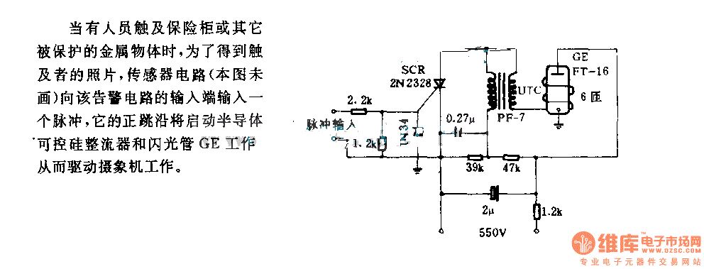
The alarm circuit diagram for safety box and other metal objects
When an individual touches the safety box or other protected metal objects, the sensor circuit generates a pulse to the alarm circuit. The positive edge of this pulse activates the semiconductor and thyristor flash GE, subsequently triggering the camera to...

Starting Capacitors
Instructions for electric motor start-run capacitors include the use of starting capacitors for air conditioner compressor motors and other electric motors like pumps. This involves diagnostic checks for start or run capacitors, including how to use a volt-ohm meter (VOM)...

Quick On-Board Junction Tester
Short circuits or broken PCB tracks can be easily identified using a multimeter. However, this tool may yield inaccurate results when assessing the efficiency of a transistor or diode unless the component is unsoldered and removed from the PCB. Additionally,...
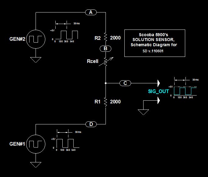
Scoobas Solution Sensing Tactic
This document serves multiple purposes, primarily to document the methods employed by a Scooba robot to detect: a) the presence of an acceptable cleaning solution being delivered to its pump, and b) the excess presence of used solution collected off...
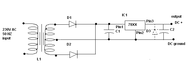
Power supply circuit design
C1 is a 1000 microfarad aluminum electrolytic capacitor. For loads less than 100mA, a 220 microfarad capacitor can be substituted. The voltage rating should be 2.5 times the output voltage.
C1 serves as a critical component in various electronic circuits, particularly...

Control cables plus anti-interference capacitors
A capacitor filter is utilized in frequency control circuits and is a common method for implementing anti-jamming measures. It addresses frequency interference noise within the wiring of the 4-20mA control loop. The anti-interference is achieved through bypass capacitors C1 and...

Add a sensor to a board and measure something with it
This week's plan is to build a device that warns of the potential for a knockdown, which is the process by which an over-canvassed ship is laid over on her beam-ends. The risk of sinking is high during this event,...