


Detection for trains on model railway
#light valve
#model railway
#train detection
#LED
#transistor
#light beam
#interruption detection
#sensor

Description: This light valve can be used for example to detect trains on model railway or a lap counter at the close racing. D3 receives a constant stream of power built around T1. When the light beam from D3 to T3 is not interrupted, led T3 and T2 is the basis of practically grounded. T2 not conduct and the LED is not lit. When the beam is interrupted, spert T3 and T2 conducts and the LED will light. Of course listen to other things like LED control between plus and the collector of T2. Please note the maximum load of 100 mA. The supply voltage may be between 4.5 and 12 volts. More: R1 = 1 kΩ R2 = 15 Ω R3 = 10 kΩ R4 = 220 Ω D1, D2 = 1N4148 D3 = infrared LED D4 = LED red T1 = BC 557B T2 = BC 547B T3 = 104 BP
This circuit functions as a light-based detection system suitable for applications such as model railway train detection or lap counting in racing scenarios. The primary component of the system is D3, an infrared LED, which emits a beam of infrared light. This light beam is directed towards T3, a phototransistor that acts as a light sensor.
The circuit operates with a supply voltage ranging from 4.5 to 12 volts, ensuring compatibility with various power sources. The maximum load for the output is specified at 100 mA, which is critical for maintaining the integrity of the components involved.
The transistor T1, a BC 557B, is configured to provide a constant current to D3, ensuring that the infrared LED operates continuously. Resistors R1 (1 kΩ) and R2 (15 Ω) are used to limit the current flowing through the circuit, protecting the components from excessive current that could lead to damage.
When the light beam emitted by D3 is uninterrupted, the base of transistors T2 (BC 547B) and T3 (104 BP) is effectively grounded, preventing T2 from conducting. As a result, the output LED (D4, a red LED) remains off. However, when the beam is interrupted—such as when a train passes through the detection zone—T3 begins to conduct, allowing current to flow through T2. This conduction activates the output LED, signaling the detection event.
Additional components include diodes D1 and D2 (1N4148), which are used for protection against reverse polarity and to ensure the stability of the circuit. Resistor R3 (10 kΩ) and R4 (220 Ω) are also strategically placed to assist in biasing the transistors and controlling the current flow within the circuit.
Overall, this light valve detection circuit is designed for simplicity and reliability, making it an effective solution for detecting moving objects in model railways or competitive racing environments.This light valve can be used for example to detect trains on model railway or a lap counter at the close racing. D3 receives a constant stream of power built around T1. When the light beam from D3 to T3 is not interrupted, led T3 and T2 is the basis of practically grounded.
T2 not conduct and the LED is not lit. When the beam is interrupted, spert T3 and T2 conducts and the LED will light. Of course listen to other things like LED control between plus and the collector of T2. Please note the maximum load of 100 mA. The supply voltage may be between 4.5 and 12 volts. R1 = 1 kW R2 = 15 ? R3 = 10 k R4 = 220 ? D1, D2 = 1N4148 D3 = infrared LED D4 = LED red T1 = BC 557B T2 = BC 547B T3 = 104 BP
This circuit functions as a light-based detection system suitable for applications such as model railway train detection or lap counting in racing scenarios. The primary component of the system is D3, an infrared LED, which emits a beam of infrared light. This light beam is directed towards T3, a phototransistor that acts as a light sensor.
The circuit operates with a supply voltage ranging from 4.5 to 12 volts, ensuring compatibility with various power sources. The maximum load for the output is specified at 100 mA, which is critical for maintaining the integrity of the components involved.
The transistor T1, a BC 557B, is configured to provide a constant current to D3, ensuring that the infrared LED operates continuously. Resistors R1 (1 kΩ) and R2 (15 Ω) are used to limit the current flowing through the circuit, protecting the components from excessive current that could lead to damage.
When the light beam emitted by D3 is uninterrupted, the base of transistors T2 (BC 547B) and T3 (104 BP) is effectively grounded, preventing T2 from conducting. As a result, the output LED (D4, a red LED) remains off. However, when the beam is interrupted—such as when a train passes through the detection zone—T3 begins to conduct, allowing current to flow through T2. This conduction activates the output LED, signaling the detection event.
Additional components include diodes D1 and D2 (1N4148), which are used for protection against reverse polarity and to ensure the stability of the circuit. Resistor R3 (10 kΩ) and R4 (220 Ω) are also strategically placed to assist in biasing the transistors and controlling the current flow within the circuit.
Overall, this light valve detection circuit is designed for simplicity and reliability, making it an effective solution for detecting moving objects in model railways or competitive racing environments.This light valve can be used for example to detect trains on model railway or a lap counter at the close racing. D3 receives a constant stream of power built around T1. When the light beam from D3 to T3 is not interrupted, led T3 and T2 is the basis of practically grounded.
T2 not conduct and the LED is not lit. When the beam is interrupted, spert T3 and T2 conducts and the LED will light. Of course listen to other things like LED control between plus and the collector of T2. Please note the maximum load of 100 mA. The supply voltage may be between 4.5 and 12 volts. R1 = 1 kW R2 = 15 ? R3 = 10 k R4 = 220 ? D1, D2 = 1N4148 D3 = infrared LED D4 = LED red T1 = BC 557B T2 = BC 547B T3 = 104 BP

SINGLE TRANSISTOR CODE PRACTICE OSCILLATOR
A 2N366 is configured as an audio feedback oscillator using an audio transformer. Adjust R1 for proper operation and the desired audio note.
The circuit utilizes a 2N366 transistor, which is a general-purpose NPN transistor, serving as the primary active component...
fun electronic circuits
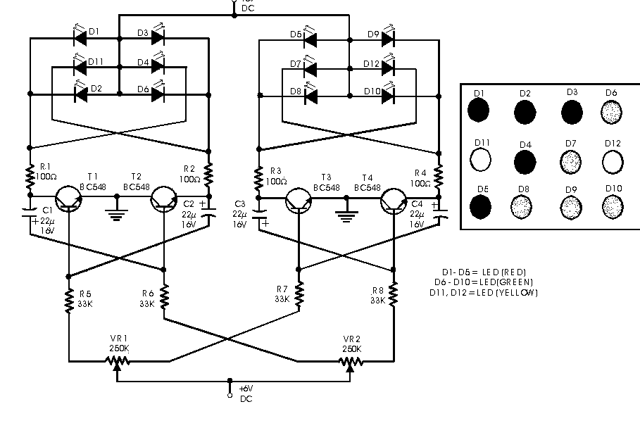
This circuit serves as a decorative element or indicator, featuring adjustable flashing or dancing speeds of LEDs and the ability to create various light patterns. It comprises two astable multivibrators; the first is constructed using transistors T1 and T2, while...
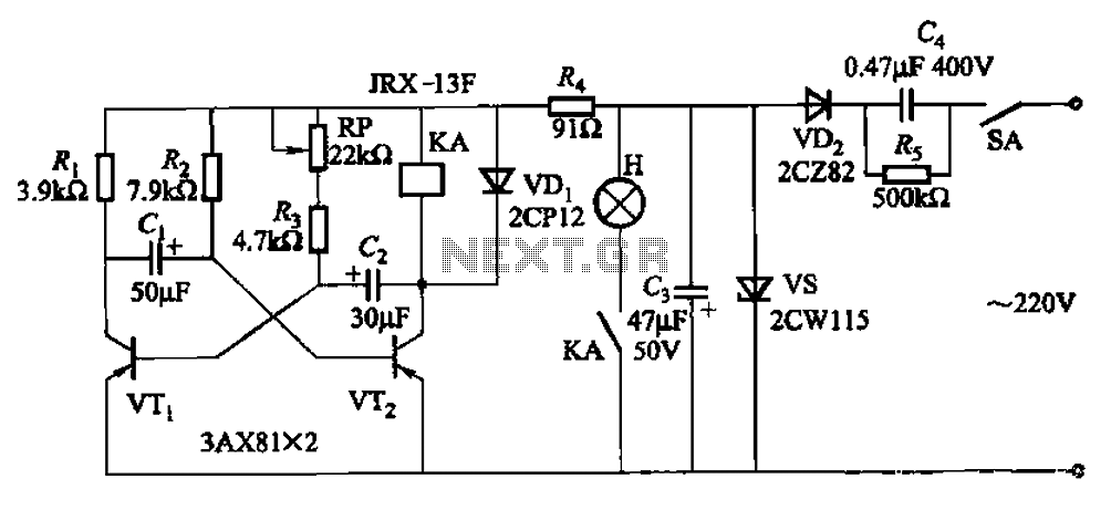
Seven blinker circuits
The circuit features a self-excited multivibrator composed of transistors VTi and VTZ. It includes an adjustment potentiometer RP and two RC networks that influence the transistors' parameters, specifically the timing for light activation and deactivation.
The described multivibrator circuit utilizes two...

Random Flasher for 8 LEDs Project
This project flashes eight LEDs in a seemingly random manner. It utilizes a 4026 combined counter and display driver integrated circuit (IC) designed for driving 7-segment LED displays. The sequence is not entirely random, as seven of the LEDs represent...

LED Flasher Using Transistor
This simple LED flasher circuit will alternately turn ON and OFF two LEDs. The first LED will illuminate when the second LED is OFF for a certain duration, and then the process will repeat.
The LED flasher circuit operates using a...

blinking-led-circuits.html
This LED series will blink alternately. The operation is determined by the NE555 integrated circuit, with transistors used to reinforce each section (20 upper, 20 lower) for optimal performance. The 555 circuit described below functions as a flashing bicycle light...

LED linear modulator
After constructing a Pulse Width Modulator for high-power LEDs, another LED modulator was developed for an optical transceiver. This project utilized a different approach, focusing solely on linear techniques for audio modulation. Similar to the PWM circuit, this circuit employs...
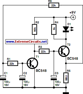
Smooth FlasherCircuit
Standard LED flashers activate the LED in a rapid on-off sequence, which can become bothersome over time. The circuit presented here offers a more gradual illumination effect.
This circuit utilizes a simple design to create a soft flashing LED effect, which...

T3SE type 3 SE
The all-transistor T3SE operates similarly to a conventional switch mode power supply (SE). Like the Tritium model, it activates when the charging current falls below a specified threshold. After the circuit is triggered, positive feedback is utilized to latch the...