


Dew sensor circuit
#dew sensor
#humidity
#moisture detection
#automatic switch
#electronic protection
#resistor sensor
#gadget safety
#condensation detection

Description: Dew (condensed moisture) adversely affects the normal performance of sensitive electronic devices. A low-cost circuit described here can be used to switch off any gadget automatically in case of excessive humidity. At the heart of the circuit is an inexpensive (resistor type) dew sensor element. Although dew sensor elements are widely used in video cassette players and recorders, these may not be easily available in the local market. However, the same can be procured from authorized service centers of reputed companies. The author used the dew sensor for FUNAI VCP model No. V.I.P. 3000A (Part No: 6808-08-04, reference no. 336) in his prototype. In practice, it is observed that all dew sensors available for video applications possess the same electrical characteristics irrespective of their physical shape/size, and hence are interchangeable and can be used in this project. The circuit is basically a switching type circuit made with the help of a popular dual op-amp IC LM358N which is configured here as a comparator. (Note that only one half of the IC is used here.) Under normal conditions, the resistance of the dew sensor is low (1 kilo-ohm or so) and thus the voltage at its non-inverting terminal (pin 3) is low compared to that at its inverting input (pin 2) terminal. The corresponding output of the comparator (at pin 1) is accordingly low and thus nothing happens in the circuit. When humidity exceeds 80 percent, the sensor resistance increases rapidly. As a result, the non-inverting pin becomes more positive than the inverting pin. This pushes up the output of IC1 to a high level. As a consequence, the LED inside the opto-coupler is energized. At the same time, LED1 provides a visual indication. The opto-coupler can be suitably interfaced to any electronic device for switching purposes. The circuit comprising diode D2, resistors R5 and R6, and capacitor C1 forms a low-voltage, low-current power supply unit. This simple arrangement obviates the requirement for a bulky and expensive step-down transformer.
The described circuit utilizes a dew sensor to monitor humidity levels and activate a switching mechanism when moisture levels become excessive. The dew sensor operates on the principle that its resistance varies significantly with humidity; under normal conditions, the resistance is approximately 1 kΩ, resulting in a low voltage at the non-inverting terminal of the LM358N op-amp. The op-amp is configured as a comparator, where the non-inverting terminal (pin 3) is connected to the dew sensor, and the inverting terminal (pin 2) is set at a reference voltage.
When the humidity rises above 80%, the resistance of the dew sensor increases, causing the voltage at the non-inverting terminal to exceed that of the inverting terminal. This condition changes the output state of the op-amp from low to high, which activates the internal LED of the opto-coupler. The opto-coupler serves as an interface to control other electronic devices, effectively allowing the circuit to disconnect or switch off the device in response to high humidity.
Additionally, LED1 provides a visual indication of the circuit's activation state, alerting users to the presence of excessive humidity. The power supply section of the circuit, which includes diode D2, resistors R5 and R6, and capacitor C1, is designed to generate a low-voltage supply from the main power source, eliminating the need for a larger step-down transformer. This design choice enhances the overall compactness and cost-effectiveness of the circuit while ensuring reliable operation in protecting sensitive electronic devices from moisture damage.Dew (condensed moisture) ad- versely affects the normal per- formance of sensitive electronic devices. A low-cost circuit described here can be used to switch off any gadget automatically in case of excessive humidity.
At the heart of the circuit is an inexpensive (resistor type) dew sensor element. Although dew sensor elements are widely used in video cassette players and recorders, these may not be easily available in local market. However, the same can be procured from authorised service centres of reputed companies. The author used the dew sensor for FUNAI VCP model No. V.I.P. 3000A (Part No: 6808-08-04, reference no. 336) in his prototype. In practice, it is observed that all dew sensors available for video application possess the same electrical characteristics irrespective of their physical shape/size, and hence are interchangeable and can be used in this project. The circuit is basically a switching type circuit made with the help of a popular dual op-amp IC LM358N which is configured here as a comparator.
(Note that only one half of the IC is used here.) Under normal conditions, resistance of the dew sensor is low (1 kilo-ohm or so) and thus the voltage at its non-inverting terminal (pin 3) is low compared to that at its inverting input (pin 2) terminal. The corresponding output of the comparator (at pin 1) is accordingly low and thus nothing happens in the circuit.
When humidity exceeds 80 per cent, the sensor resistance increases rapidly. As a result, the non-inverting pin becomes more positive than the inverting pin. This pushes up the output of IC1 to a high level. As a consequence, the LED inside the opto-coupler is energised. At the same time LED1 provides a visual indication. The opto-coupler can be suitably interfaced to any electronic device for switching purpose. Circuit comprising diode D2, resistors R5 and R6 and capacitor C1 forms a low-voltage, low-current power supply unit. This simple arrangement obviates the requirement for a bulky and expensive step-down transformer.
The described circuit utilizes a dew sensor to monitor humidity levels and activate a switching mechanism when moisture levels become excessive. The dew sensor operates on the principle that its resistance varies significantly with humidity; under normal conditions, the resistance is approximately 1 kΩ, resulting in a low voltage at the non-inverting terminal of the LM358N op-amp. The op-amp is configured as a comparator, where the non-inverting terminal (pin 3) is connected to the dew sensor, and the inverting terminal (pin 2) is set at a reference voltage.
When the humidity rises above 80%, the resistance of the dew sensor increases, causing the voltage at the non-inverting terminal to exceed that of the inverting terminal. This condition changes the output state of the op-amp from low to high, which activates the internal LED of the opto-coupler. The opto-coupler serves as an interface to control other electronic devices, effectively allowing the circuit to disconnect or switch off the device in response to high humidity.
Additionally, LED1 provides a visual indication of the circuit's activation state, alerting users to the presence of excessive humidity. The power supply section of the circuit, which includes diode D2, resistors R5 and R6, and capacitor C1, is designed to generate a low-voltage supply from the main power source, eliminating the need for a larger step-down transformer. This design choice enhances the overall compactness and cost-effectiveness of the circuit while ensuring reliable operation in protecting sensitive electronic devices from moisture damage.Dew (condensed moisture) ad- versely affects the normal per- formance of sensitive electronic devices. A low-cost circuit described here can be used to switch off any gadget automatically in case of excessive humidity.
At the heart of the circuit is an inexpensive (resistor type) dew sensor element. Although dew sensor elements are widely used in video cassette players and recorders, these may not be easily available in local market. However, the same can be procured from authorised service centres of reputed companies. The author used the dew sensor for FUNAI VCP model No. V.I.P. 3000A (Part No: 6808-08-04, reference no. 336) in his prototype. In practice, it is observed that all dew sensors available for video application possess the same electrical characteristics irrespective of their physical shape/size, and hence are interchangeable and can be used in this project. The circuit is basically a switching type circuit made with the help of a popular dual op-amp IC LM358N which is configured here as a comparator.
(Note that only one half of the IC is used here.) Under normal conditions, resistance of the dew sensor is low (1 kilo-ohm or so) and thus the voltage at its non-inverting terminal (pin 3) is low compared to that at its inverting input (pin 2) terminal. The corresponding output of the comparator (at pin 1) is accordingly low and thus nothing happens in the circuit.
When humidity exceeds 80 per cent, the sensor resistance increases rapidly. As a result, the non-inverting pin becomes more positive than the inverting pin. This pushes up the output of IC1 to a high level. As a consequence, the LED inside the opto-coupler is energised. At the same time LED1 provides a visual indication. The opto-coupler can be suitably interfaced to any electronic device for switching purpose. Circuit comprising diode D2, resistors R5 and R6 and capacitor C1 forms a low-voltage, low-current power supply unit. This simple arrangement obviates the requirement for a bulky and expensive step-down transformer.

Dew sensor
Dew sensor. Dew (condensed moisture) adversely affects the normal performance of sensitive electronic devices. A low-cost circuit described here can be used to.
The dew sensor circuit is designed to detect the presence of condensed moisture, which can significantly impair the...

Simple humidity detector
The primary function of this circuit is to activate a buzzer or a relay whenever the humidity level reaches a specified threshold. The main component is a memory element based on a flip-flop made up of gates and integrated circuits...

Humidity detector circuit electronic project
This humidity detector circuit diagram is straightforward and utilizes a limited number of components. It can be employed to activate electronic devices when the detector identifies a specific humidity level. The sensor is made from two copper pieces positioned close...
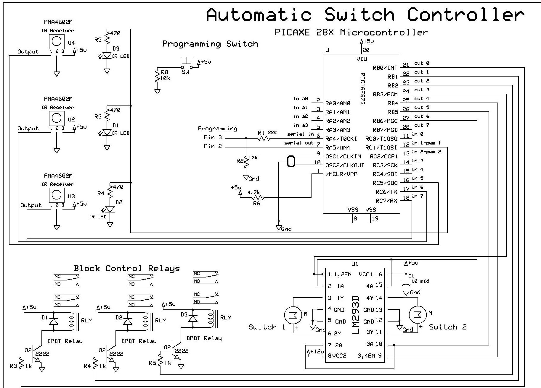
Automatic Switch Project
The objective of this controller project is to achieve automatic block and switch control for five separate engines operating on two independent loops of track. Each loop has both public and hidden sections. The inner loop accommodates three trains, while...

Simple Moisture Detector
The function of this circuit is to sound a buzzer or, optionally, actuate a relay when a specific moisture level is detected between a pair of probes. The circuit incorporates a memory element in the form of a flip-flop (IC1a-IC1b),...
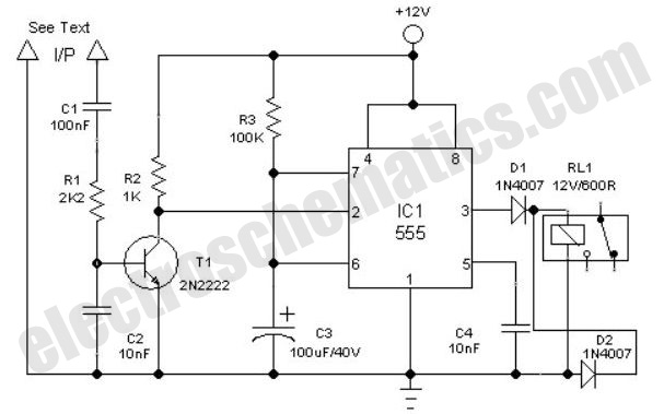
Clock Alarm Light Switch Circuit
This is a simple automatic light switch circuit designed for bedrooms. After construction, the input terminals of this circuit should be connected in parallel to the intended lighting fixture.
The automatic light switch circuit utilizes a light-dependent resistor (LDR) as the...

Humidity Sensor
Introduction Humidity is the amount of water vapor in the air, expressed as a percentage of the maximum amount that the air could hold at the given temperature.
Humidity measurement is critical in various applications, including meteorology, HVAC systems, agriculture, and...
Humidity Sensor
Introduction Humidity is the amount of water vapor in the air, expressed as a percentage of the maximum amount that the air could hold at the given temperature.
Humidity measurement is critical in various applications, including meteorology, HVAC systems, agriculture, and...

Quartz Controlled Bedroom Light Switch
This is a simple automatic light switch circuit designed for bedrooms. After construction, connect the input terminals of this circuit in parallel to the existing light fixture.
The automatic light switch circuit operates using a photoresistor (LDR) and a transistor as...