


Differential Light
#CdS cells
#light sensor
#variable resistor
#Lego brick
#adjustable circuit
#photoresistor
#light detection
#DIY sensor
#compact circuit
#educational project

Description: Construct a circuit on a 1-inch square circuit board. Position the variable resistor so that it can be adjusted from one of the edges. Attach the CdS cells at the opposite end, but not at the edge. Drill out two pins near the center of one of the long sides of a Lego brick. Create four notches at the base of that same side for the CdS cell leads to exit. Remove all internal components of the brick. Solder two short 3/16 rods to wires that connect to the circuit where it is labeled RCX. The rods must be short enough to fit into the holes in the top brick without contacting the leads from the CdS cells. Connect this sensor to the RCX and configure it for light detection. When one side receives more light, it will register a high reading, while the other side will register a low reading. Adjust the resistor to ensure both sides respond similarly. It may be beneficial to modify the angle of the cells or attach a piece of plastic between them to enhance directionality. CdS cells function as resistors that decrease resistance as light exposure increases. Therefore, it is possible to create a light sensor that detects variations in light and dark by connecting one cell directly to the RCX.
The described circuit utilizes a 1-inch square circuit board as the foundation for a light-sensing application. The variable resistor is strategically positioned at one edge for easy manual adjustment. The placement of the CdS cells at the opposite end, away from the edge, minimizes interference and facilitates better light detection.
The integration of the Lego brick serves as a housing for the circuit, where two pins are drilled near the center of one long side to secure the assembly. The four notches created at the base allow for the CdS cell leads to exit the brick without obstruction. This design ensures that the internal components of the Lego brick are completely removed, providing ample space for the circuit and preventing any unintended short circuits.
The connection of two short 3/16 rods to the circuit labeled RCX is crucial for interfacing with the Lego system. These rods are designed to fit into the holes of the top brick, ensuring that they do not interfere with the CdS cell leads. This careful consideration in design allows for seamless integration with the RCX, enabling it to function effectively as a light sensor.
When configured for light detection, the sensor will respond to variations in light intensity. The output readings will indicate a high value when one side is exposed to more light compared to the other side, which will register a low value. The adjustment of the variable resistor is essential for calibrating the system, allowing both sides to exhibit similar responses to light changes.
To enhance the directional sensitivity of the CdS cells, adjustments to their angle or the addition of a plastic barrier between them may be necessary. This modification can help focus the sensor's detection capabilities, improving its performance in distinguishing between light and dark environments.
CdS cells operate on the principle of photoconductivity, functioning as resistors that decrease their resistance in response to increased light exposure. This characteristic enables the creation of a simple yet effective light sensor, capable of detecting light and dark conditions by connecting a single CdS cell directly to the RCX for basic light sensing applications.Build circuit on a 1" square circuit board. Position the variable resister so that it can be adjusted from one of the edges. Attach the CdS cells at the other end but not at the edge. Drill out two pins next to the center of one of the long sides of a Lego brick. Make four notches at the base of that same side for the CdS cell leads to come out. R emove all of the insides of the brick. Solder two short 3/16 rods to wires that connect to the circuit where it is labeled RCX. Rods must be short enough to fit into the holes in the top brick and not touch the leads from the CdS cells. Plug this sensor into the RCX and set it for light. When one side has more light it will read high, when the other side has more light it will read low. Adjust the resister to get each side to react about the same way. You might want to adjust the angle of your cells or glue a piece of plastic between them to get it more directional.
CdS cells are simply resisters that loose resistance as more light hits it. So you could make a light sensor that detects just light and dark by hooking up one cell directly to the RCX.
The described circuit utilizes a 1-inch square circuit board as the foundation for a light-sensing application. The variable resistor is strategically positioned at one edge for easy manual adjustment. The placement of the CdS cells at the opposite end, away from the edge, minimizes interference and facilitates better light detection.
The integration of the Lego brick serves as a housing for the circuit, where two pins are drilled near the center of one long side to secure the assembly. The four notches created at the base allow for the CdS cell leads to exit the brick without obstruction. This design ensures that the internal components of the Lego brick are completely removed, providing ample space for the circuit and preventing any unintended short circuits.
The connection of two short 3/16 rods to the circuit labeled RCX is crucial for interfacing with the Lego system. These rods are designed to fit into the holes of the top brick, ensuring that they do not interfere with the CdS cell leads. This careful consideration in design allows for seamless integration with the RCX, enabling it to function effectively as a light sensor.
When configured for light detection, the sensor will respond to variations in light intensity. The output readings will indicate a high value when one side is exposed to more light compared to the other side, which will register a low value. The adjustment of the variable resistor is essential for calibrating the system, allowing both sides to exhibit similar responses to light changes.
To enhance the directional sensitivity of the CdS cells, adjustments to their angle or the addition of a plastic barrier between them may be necessary. This modification can help focus the sensor's detection capabilities, improving its performance in distinguishing between light and dark environments.
CdS cells operate on the principle of photoconductivity, functioning as resistors that decrease their resistance in response to increased light exposure. This characteristic enables the creation of a simple yet effective light sensor, capable of detecting light and dark conditions by connecting a single CdS cell directly to the RCX for basic light sensing applications.Build circuit on a 1" square circuit board. Position the variable resister so that it can be adjusted from one of the edges. Attach the CdS cells at the other end but not at the edge. Drill out two pins next to the center of one of the long sides of a Lego brick. Make four notches at the base of that same side for the CdS cell leads to come out. R emove all of the insides of the brick. Solder two short 3/16 rods to wires that connect to the circuit where it is labeled RCX. Rods must be short enough to fit into the holes in the top brick and not touch the leads from the CdS cells. Plug this sensor into the RCX and set it for light. When one side has more light it will read high, when the other side has more light it will read low. Adjust the resister to get each side to react about the same way. You might want to adjust the angle of your cells or glue a piece of plastic between them to get it more directional.
CdS cells are simply resisters that loose resistance as more light hits it. So you could make a light sensor that detects just light and dark by hooking up one cell directly to the RCX.

Light Pollution Meter
My circuit adds a transistor, to add feedback, and two resistors, to tailor the range of the control, with the result that a single-turn potentiometer gives a control range of about 2 to 30 microamps. I installed my circuit in...
light sensor
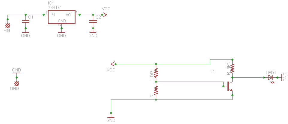
When connecting this element in a voltage divider configuration, a high and low signal can be generated based on the amount of light detected by the sensor. An NPN transistor configured as an inverter further filters this signal to produce...

sun up alarm schematics
The Up Alarm is designed to provide an audible alert when sunlight is detected or when a light source is activated in a dark environment. It can also be utilized to sense various light sources such as beams or headlights....

Photoresistor LDR light control switch circuit diagram
The circuit depicted involves a photoresistor (LDR) connected to a transistor, which operates at either a high or low level based on light conditions. The amplification factor of the transistor is 100, which is adequate for the application. The resistance...
Most Popular Circuits
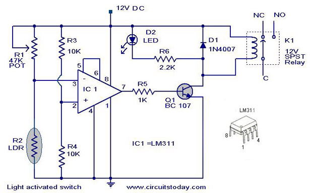
A simple light-activated switch circuit diagram utilizes the National Semiconductor comparator IC LM311 and a light-dependent resistor (LDR). The circuit functions as a voltage comparator, with the non-inverting input of IC1 receiving a reference voltage of 6V through resistors R3...

Visible and Infrared Light Detectors
The sensors used are silicon phototransistors and Cadmium Sulfide (CdS) photocells. Both of these sensors allow less current to flow when they are dark than when lighted. Phototransistors change their conductance while photocells change their resistance depending on the intensity...

6V Light Barrier Sensor Detector
The following circuit illustrates a Light Barrier Sensor Detector Circuit Diagram. Features include a single transistor, an adjustable potentiometer, and a 6V power supply.
The Light Barrier Sensor Detector Circuit is designed to detect the presence of an object by utilizing...

home-made light-operated camera trigger
This device is designed to capture images of moving objects by activating a camera or flashgun when one or two light beams are interrupted. Originally intended for photographing insects in flight, it can also be utilized for projectiles and other...

Adjustable light detection switch
R2 sets the circuit's threshold. When the light intensity at the PCI's surface decreases, the resistance of PCI, a cadmium-sulfide photo-resistor, increases. This results in a decrease in voltage at the inverting input of the 741 operational amplifier. When the...