


Digital Compass for PC
#digital compass
#Hall effect
#microcontroller
#navigation
#PC interface
#robotics
#sensor
#magnetic field
#solid-state

Description: The digital navigation PC board may be configured for a number of navigation functions. It may be made into a simple visual digital compass, or a microcontroller based compass. The microcontroller based compass can be used for mobile robotics or a PC based compass. The sensor used on the PC Board is the 1490 digital compass manufactured by Robson Company. This sensor is a solid-state Hall effect device. It is sensitive enough to detect the Earth's weak magnetic field. When rotated it can display the position of the four cardinal points on a compass: North (N), South (S), East (E), and West (W), as well as the intermediate directions: North East (NE), North West (NW), South East (SE), and South West (SW). The sensor is dampened to approximate the speed of a liquid filled compass. The dampening prevents over swinging the direction. In addition, the built-in hysteresis prevents flutter when near a switching direction. The 1490 device is sensitive to tilt, and any tilt greater than 12 degrees will create directional errors. The bottom of the device has 12 leads arranged in four groups of three leads. Looking at the device from the top, each group of leads are labeled 1, 2, and 3. The leads labeled 1 are connected to Vcc (+5V). Leads numbered 2 are connected to ground. The leads labeled 3 are the output leads. The output leads of the device are equivalent to an open collector of an NPN transistor. Each output is capable of sinking 20 mA continuously or up to 25 mA intermittently.
The digital navigation PC board serves as a versatile platform for various navigation applications, primarily utilizing the 1490 digital compass sensor from Robson Company. This solid-state Hall effect sensor is adept at detecting the Earth's magnetic field, making it suitable for both simple visual compasses and more complex microcontroller-based systems.
In operation, the sensor can accurately indicate the four cardinal directions (N, S, E, W) and the intermediate directions (NE, NW, SE, SW) when the board is rotated. This capability is enhanced by a dampening mechanism that mimics the response of a traditional liquid-filled compass, reducing overshooting and providing stable readings. The built-in hysteresis feature further stabilizes output by preventing fluctuations when the sensor is near a directional threshold.
The 1490 sensor's design includes a sensitivity to tilt, which is a critical consideration in applications where the device may not be perfectly level. Any tilt exceeding 12 degrees can introduce significant directional inaccuracies, thus the installation and orientation of the board must be carefully managed.
The sensor's lead configuration consists of 12 pins organized into four groups of three. The first group of leads (labeled 1) is connected to a power supply of +5V (Vcc), while the second group (labeled 2) is grounded. The third group (labeled 3) serves as the output leads, functioning similarly to an open collector output of an NPN transistor. Each output can handle a continuous current of 20 mA, with a maximum intermittent current of 25 mA, allowing for reliable interfacing with microcontrollers or other processing units.
This configuration makes the digital navigation PC board an effective tool for mobile robotics, PC-based compass applications, and other navigation functions, providing both flexibility and precision in directional sensing.The digital navigation PC board may be configured for a number of navigation functions, see figure 1. It may be made into a simple visual digital compass, or a microcontroller based compass. The microcontroller based compass can be used for mobile robotics or a PC based compass. The sensor used on the PC Board is the 1490 digital compass manufactured by Robson Company, see figure 2.
This sensor is a solid-state Hall effect device. It is sensitive enough to detect the Earth's weak magnetic field. When rotated it can display the position of the four cardinal points on a compass, North (N), South (S), East (E) and West (W). As well as the intermediate directions: North East (NE), North West (NW), South East (SE), and South West (SW), see figure 3.
The sensor is dampened to approximate the speed of a liquid filled compass. The dampening prevents over swinging the direction. In addition the built in hysteresis prevents flutter when near a switching direction. The 1490 device is sensitive to tilt. Any tilt greater than 12 degrees will create directional errors. The bottom of the device has 12 leads arranged in four groups of three leads. Looking at the device from the top each group of leads are labeled 1, 2 and 3. The leads labeled 1 are connected to Vcc (+5V). Leads numbered 2 are connected to ground. And the leads labeled 3 are our output leads. The output leads of the device are equivalent to an open collector of an NPN transistor, see figure 4. Each output is capable of sinking 20 mA continuously or up to 25 mA intermittently.
The digital navigation PC board serves as a versatile platform for various navigation applications, primarily utilizing the 1490 digital compass sensor from Robson Company. This solid-state Hall effect sensor is adept at detecting the Earth's magnetic field, making it suitable for both simple visual compasses and more complex microcontroller-based systems.
In operation, the sensor can accurately indicate the four cardinal directions (N, S, E, W) and the intermediate directions (NE, NW, SE, SW) when the board is rotated. This capability is enhanced by a dampening mechanism that mimics the response of a traditional liquid-filled compass, reducing overshooting and providing stable readings. The built-in hysteresis feature further stabilizes output by preventing fluctuations when the sensor is near a directional threshold.
The 1490 sensor's design includes a sensitivity to tilt, which is a critical consideration in applications where the device may not be perfectly level. Any tilt exceeding 12 degrees can introduce significant directional inaccuracies, thus the installation and orientation of the board must be carefully managed.
The sensor's lead configuration consists of 12 pins organized into four groups of three. The first group of leads (labeled 1) is connected to a power supply of +5V (Vcc), while the second group (labeled 2) is grounded. The third group (labeled 3) serves as the output leads, functioning similarly to an open collector output of an NPN transistor. Each output can handle a continuous current of 20 mA, with a maximum intermittent current of 25 mA, allowing for reliable interfacing with microcontrollers or other processing units.
This configuration makes the digital navigation PC board an effective tool for mobile robotics, PC-based compass applications, and other navigation functions, providing both flexibility and precision in directional sensing.The digital navigation PC board may be configured for a number of navigation functions, see figure 1. It may be made into a simple visual digital compass, or a microcontroller based compass. The microcontroller based compass can be used for mobile robotics or a PC based compass. The sensor used on the PC Board is the 1490 digital compass manufactured by Robson Company, see figure 2.
This sensor is a solid-state Hall effect device. It is sensitive enough to detect the Earth's weak magnetic field. When rotated it can display the position of the four cardinal points on a compass, North (N), South (S), East (E) and West (W). As well as the intermediate directions: North East (NE), North West (NW), South East (SE), and South West (SW), see figure 3.
The sensor is dampened to approximate the speed of a liquid filled compass. The dampening prevents over swinging the direction. In addition the built in hysteresis prevents flutter when near a switching direction. The 1490 device is sensitive to tilt. Any tilt greater than 12 degrees will create directional errors. The bottom of the device has 12 leads arranged in four groups of three leads. Looking at the device from the top each group of leads are labeled 1, 2 and 3. The leads labeled 1 are connected to Vcc (+5V). Leads numbered 2 are connected to ground. And the leads labeled 3 are our output leads. The output leads of the device are equivalent to an open collector of an NPN transistor, see figure 4. Each output is capable of sinking 20 mA continuously or up to 25 mA intermittently.

Robo Atmega328p project
This project was designed to introduce a friend to microcontrollers and circuits using various functionalities and spare parts. A PS2 numpad was utilized as the key entry mechanism, which was found at a thrift store and included the necessary connector....

Training Boxing timer schematic
A timer is being developed for circuit training or boxing training. The timer does not require any external input, except for a reset function. The project can be simplified using a microcontroller, such as the PIC12F635, which is cost-effective at...

Electronic TIC TAC TOE
This project is not to introduce Tic Tac Toe. Everyone knows this game. It is to introduce two features: bi-coloured LEDs, microcontrollers, and the skill of writing an ALGORITHM. You can use the project to learn the skills of creating...

Automatic Room light Control With Bi Directional Visitor Counter
The objective of this project is to create a controller-based model that counts the number of individuals entering a specific room and activates the lighting accordingly. This is achieved through the use of sensors that detect the current number of...

87C51 Selling Leads
This circuit utilizes an 87C57 microcontroller along with several peripherals to convert X-10 power-line carrier-code formats from a personal computer for use with an X-10 power-line interface in a home control system. Software details can be found in the reference....

High Resolution Digital Weigh-scale Design Using Z8 Encore! ?® Microcontrollers
The SP6691 circuit is designed to provide a high output voltage using a lower voltage boost regulator by incorporating a charge pump circuit. This configuration can convert a standard 30V boost regulator into a 60V boost regulator if necessary. Testing...

Magnetic Field Meter
Using a pickup coil to drive an amplifier (IC3A-B-C-D), this meter circuit can be directly calibrated in field intensity units. R3/C3 and R12/C7 establish a frequency roll-off that compensates for the pickup coil's sensitivity and set a 20 kHz cut-off...

simple gauss detection switch
An ultra-sensitive gauss meter circuit schematic serves as a simple indicator with no measurement, scaling, or accuracy. It consists of a Hall effect device or integrated circuit on a board with power supply inputs, minimal signal conditioning comprising approximately a...
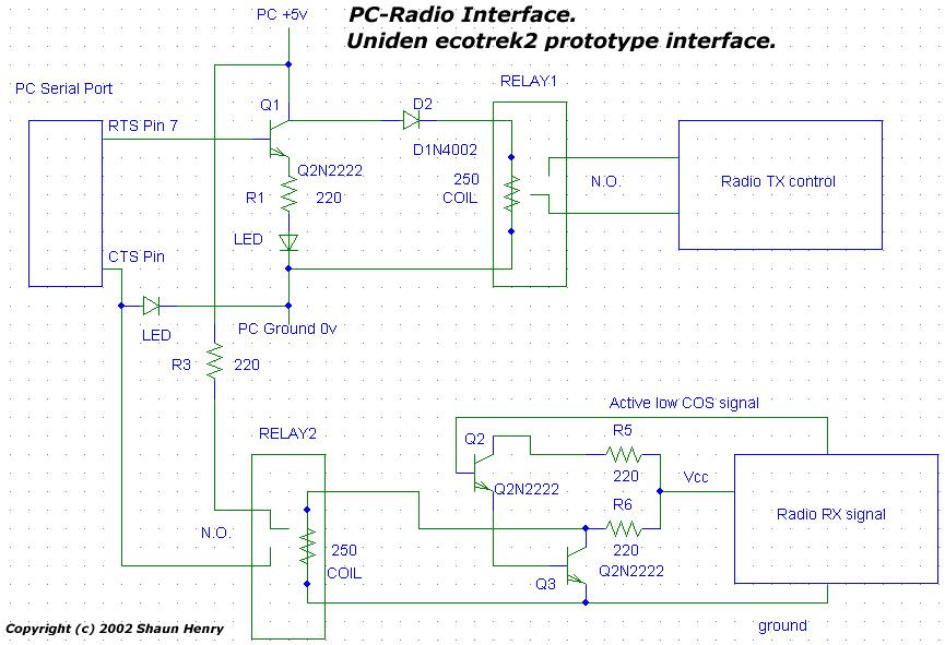
pc frs radio control
Tutorials, reviews, and software regarding airsoft. This project illustrates how to connect a PC to a small FRS radio via a simple RS-232 interface. There are several reasons for this connection.
This project focuses on establishing a communication link between a...