


Electronic mousetrap power-saving circuit

Description: Power-saving electronic mousetrap. This example describes the minimal power consumption, which only occurs when a mouse enters the control zone during foraging activities. After a 30-second delay, the system enters a wait state, making it suitable for outdoor use. The working principle of the electronic mousetrap is depicted in the electrical circuit diagram, which includes components VT1 to VT4 that form the control circuit. Their function is to detect whether a mouse has entered the control system area, triggering an alarm and generating the necessary control voltage. The alarm circuit, comprising IC and VT5, activates a speaker to emit a sound when a mouse is detected. VT6 and associated components create a transmitter operating at a frequency range of 88 to 108 MHz with a transmission distance exceeding 1 km for remote monitoring. The voltage generating circuit, including VT7 and VD2, produces several hundred to several thousand volts to eliminate mice that enter the controlled area. When the manual switch SA is closed, power is supplied to the control circuit, causing VT1 to VT4 to remain inactive, which keeps the alarm and high-voltage circuits de-energized. When a mouse enters and triggers the circuit between electrodes A and B, the resistive connection activates VT1 to VT4, closing relay K and powering the alarm and high-voltage generation. The power supply then charges through VT1 and VT2, allowing for a 30-second delay after the mouse has left before the relay resets. This design prevents prolonged operation, reducing unnecessary power consumption. The alarm IC signals through the speaker, producing a sound, while a high-frequency oscillator made up of VT6 emits a signal externally. Additionally, light-emitting diodes LED1 and LED2 illuminate to further deter the mice. As a result, the mice are frightened and flee, triggering the high-voltage system that eliminates them. Upon receiving an alarm signal, custodial staff can respond quickly using an FM radio to clear the area of any deceased rodents.
The electronic mousetrap employs a sophisticated control circuit that minimizes power usage while maintaining effective rodent detection and elimination capabilities. The circuit is designed around several key components that work in conjunction to ensure reliable operation. The control circuit, consisting of transistors VT1 to VT4, is responsible for monitoring the control zone. These transistors are configured to form a sensitive detection mechanism that responds to the presence of a mouse. When the mouse enters the designated area, it completes an electrical path between electrodes A and B, which activates the control circuit.
The alarm system is critical for alerting nearby personnel. It utilizes an integrated circuit (IC) paired with a transistor (VT5) to drive a speaker that emits an audible alarm. This feature ensures that custodial staff are notified promptly when a mouse is detected, allowing for timely intervention.
For remote monitoring, the transmitter circuit, led by VT6, operates within the FM frequency range of 88 to 108 MHz. This design allows for effective communication over distances greater than 1 km, enabling staff to monitor the mousetrap's status without being physically present.
The high-voltage generation circuit, which includes VT7 and VD2, is designed to deliver lethal voltage levels to eliminate any mice that enter the control area. This circuit is activated only when the control circuit confirms the presence of a mouse, ensuring that the high-voltage system remains inactive during idle periods to conserve energy.
The inclusion of a manual switch (SA) allows for easy activation of the system, providing flexibility in deployment. The design incorporates a delay mechanism of approximately 30 seconds after the mouse leaves the area, which prevents unnecessary activation of the high-voltage circuit and helps to extend the lifespan of the components.
Overall, the power-saving electronic mousetrap is a well-engineered solution that combines efficiency with effectiveness in rodent control, making it a viable option for outdoor environments where traditional traps may be less practical.Power-saving electronic mousetrap This example describes the usual minimal power consumption, only when the mouse enters the control zone when foraging work, and then after the 30s delay fork into the wait state, it is suitable for outdoor use mousetrap. (1) Working principle of 23-11 knots electrical circuit diagram of the electronic mousetrap. VT1 ~ VT4 composed of a control circuit and related components, and its role is to enter the notification whether the mouse control system area, and alarm and control voltage generating electrical power to the road.
IC, VT5 etc. alarm circuit, when a rat entered the control area, IC alarm signal by pushing VT5 speaker microphone BL sound. VT6 and the peripheral element pieces composed transmitter operating frequency 88 ~ 108MHz, launch distance of lkm above, in order to implement remote monitoring.
VT7, T, etc. VD2 voltage generating circuit, the output of several hundred to several thousand volts pressure, to kill the mice enter controlled areas. When the manual switch SA is closed, the power supply to the control circuit power, then VTI-VT4 are closed, following the electrical alarm and t K is not energized high voltage circuit does not work.
When the mouse enters that triggers when the equivalent of between A, B electrodes, a resistor. VT1 ~ VT4- are conduction, the relay K pull its contact K is closed, the alarm and high voltage generating power supply circuit is turned on. At the same time, the power supply to the cz charged by VT1, VT2, so that when the mice after departure triggers a relay delay about 30s closed.
VT7 avoid prolonged work impaired, but also reduce the power consumption of useless. Alarm IC sent all the way through the speaker BL charcoal sound. Another way was prepared by a high-frequency oscillator consisting of VT6, and emitted outside. At the same time, the light emitting diode LED1, LED2 light. Since then the mice frightened and fled into the high-voltage triggers a t Arab was killed. Upon receipt of an alarm signal in the distance custodial staff with FM radio, to the scene in time to clear the dead rats.
The electronic mousetrap employs a sophisticated control circuit that minimizes power usage while maintaining effective rodent detection and elimination capabilities. The circuit is designed around several key components that work in conjunction to ensure reliable operation. The control circuit, consisting of transistors VT1 to VT4, is responsible for monitoring the control zone. These transistors are configured to form a sensitive detection mechanism that responds to the presence of a mouse. When the mouse enters the designated area, it completes an electrical path between electrodes A and B, which activates the control circuit.
The alarm system is critical for alerting nearby personnel. It utilizes an integrated circuit (IC) paired with a transistor (VT5) to drive a speaker that emits an audible alarm. This feature ensures that custodial staff are notified promptly when a mouse is detected, allowing for timely intervention.
For remote monitoring, the transmitter circuit, led by VT6, operates within the FM frequency range of 88 to 108 MHz. This design allows for effective communication over distances greater than 1 km, enabling staff to monitor the mousetrap's status without being physically present.
The high-voltage generation circuit, which includes VT7 and VD2, is designed to deliver lethal voltage levels to eliminate any mice that enter the control area. This circuit is activated only when the control circuit confirms the presence of a mouse, ensuring that the high-voltage system remains inactive during idle periods to conserve energy.
The inclusion of a manual switch (SA) allows for easy activation of the system, providing flexibility in deployment. The design incorporates a delay mechanism of approximately 30 seconds after the mouse leaves the area, which prevents unnecessary activation of the high-voltage circuit and helps to extend the lifespan of the components.
Overall, the power-saving electronic mousetrap is a well-engineered solution that combines efficiency with effectiveness in rodent control, making it a viable option for outdoor environments where traditional traps may be less practical.Power-saving electronic mousetrap This example describes the usual minimal power consumption, only when the mouse enters the control zone when foraging work, and then after the 30s delay fork into the wait state, it is suitable for outdoor use mousetrap. (1) Working principle of 23-11 knots electrical circuit diagram of the electronic mousetrap. VT1 ~ VT4 composed of a control circuit and related components, and its role is to enter the notification whether the mouse control system area, and alarm and control voltage generating electrical power to the road.
IC, VT5 etc. alarm circuit, when a rat entered the control area, IC alarm signal by pushing VT5 speaker microphone BL sound. VT6 and the peripheral element pieces composed transmitter operating frequency 88 ~ 108MHz, launch distance of lkm above, in order to implement remote monitoring.
VT7, T, etc. VD2 voltage generating circuit, the output of several hundred to several thousand volts pressure, to kill the mice enter controlled areas. When the manual switch SA is closed, the power supply to the control circuit power, then VTI-VT4 are closed, following the electrical alarm and t K is not energized high voltage circuit does not work.
When the mouse enters that triggers when the equivalent of between A, B electrodes, a resistor. VT1 ~ VT4- are conduction, the relay K pull its contact K is closed, the alarm and high voltage generating power supply circuit is turned on. At the same time, the power supply to the cz charged by VT1, VT2, so that when the mice after departure triggers a relay delay about 30s closed.
VT7 avoid prolonged work impaired, but also reduce the power consumption of useless. Alarm IC sent all the way through the speaker BL charcoal sound. Another way was prepared by a high-frequency oscillator consisting of VT6, and emitted outside. At the same time, the light emitting diode LED1, LED2 light. Since then the mice frightened and fled into the high-voltage triggers a t Arab was killed. Upon receipt of an alarm signal in the distance custodial staff with FM radio, to the scene in time to clear the dead rats.

Automatic plant waterer
The unit consists of a sensor, timer, and electric water pump. The sensor is embedded in the soil, and when dry, the electronics operate the water pump for a preset time. The circuit is composed of a level-sensitive Schmitt trigger,...

Low-Power Ring Counter (Less Than 6 Mw)
The ring counter operates from 1.0 to 6.0 V and requires only 6 mW at 1.5 V. The reset pulse activates the first stage with its trailing edge. The maximum shift pulse width increases with voltage and approaches 70 µs...

Automatic Room light Control With Bi Directional Visitor Counter
The objective of this project is to create a controller-based model that counts the number of individuals entering a specific room and activates the lighting accordingly. This is achieved through the use of sensors that detect the current number of...

Low-Power Metronome
This metronome operates on a current of only 0.25 mA, making it suitable for battery-powered applications. It offers a tempo range from 34 to 246 beats per minute. The circuit can utilize a CMOS timer, such as the LM555 CN...

Field disturbance sensor-alarm
The change in ambient light triggers the alarm by changing the resistance of LDR1 and LDR2.
The circuit utilizes two light-dependent resistors (LDR1 and LDR2) to detect variations in ambient light levels. LDRs are passive components that exhibit a change in...

Power-Saving Intermittent Converter
This circuit switches its DC/DC converter, IC1, off whenever the large filter capacitor, C6, has sufficient charge to power the load. This particular circuit uses a DC/DC converter that produces 115 Vdc from a 9 Vdc input; it can be...

Pots water alarm circuit
The flowers in pots require watering, as relying solely on the observation of moist soil surfaces can be unreliable. To address this issue, a flower watering indicator has been developed. This circuit includes a field effect transistor (VT1), a second...
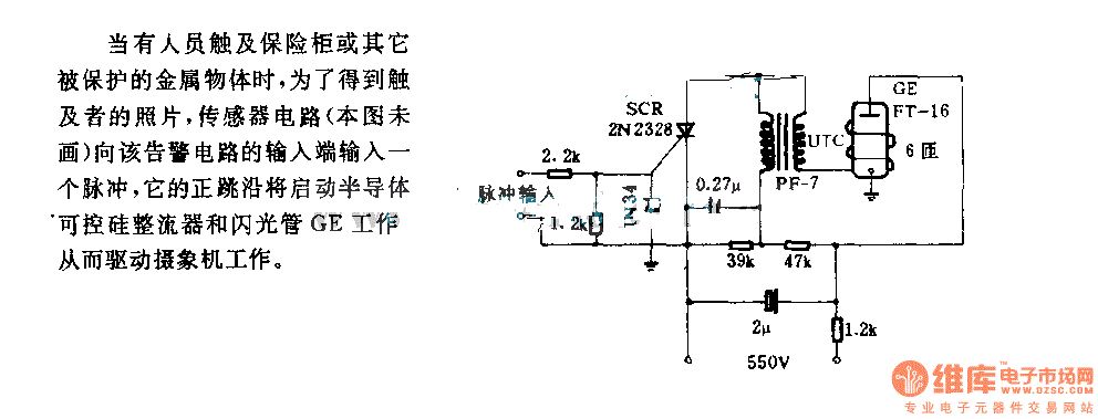
The alarm circuit diagram for safety box and other metal objects
When an individual touches the safety box or other protected metal objects, the sensor circuit generates a pulse to the alarm circuit. The positive edge of this pulse activates the semiconductor and thyristor flash GE, subsequently triggering the camera to...
The alarm circuit diagram for safety box and other metal objects
When an individual touches the safety box or other protected metal objects, the sensor circuit generates a pulse to the alarm circuit. The positive edge of this pulse activates the semiconductor and thyristor flash GE, subsequently triggering the camera to...