


EM Field Probe with Meter
#EM field
#RF detector
#audio detector
#op-amp
#electromagnetic sensor
#frequency response
#headphone monitor
#stray field detector
#probe

Description: This tester is designed to locate stray electromagnetic (EM) fields. It will easily detect both audio and RF signals up to frequencies of around 100kHz. Note, however that this circuit is NOT a metal detector, but will detect metal wiring if it conducting ac current. Frequency response is from 50Hz to about 100kHz gain being rolled off by the 150p capacitor, the gain of the op-amp and input capacitance of the probe cable. Stereo headphones may be used to monitor audio frequencies at the socket, SK1. More: Meter Circuit: The output signal from the op-amp is an ac voltage at the frequency of the electro-magnetic field. This voltage is further amplified by the BC109C transistor, before being full wave rectified and fed to the meter circuit. The meter is a sm
This electromagnetic field (EMF) tester circuit is designed to accurately detect stray EM fields across a frequency range from 50 Hz to approximately 100 kHz. The circuit employs an operational amplifier (op-amp) as the primary signal processing unit, which amplifies the incoming alternating current (AC) signals generated by nearby electromagnetic sources. The op-amp's gain is influenced by the input capacitance of the probe cable, along with a 150 pF capacitor that rolls off the gain at higher frequencies, ensuring that the circuit remains sensitive to lower frequency signals while preventing distortion at the upper end of its operational range.
The output from the op-amp is an AC voltage that corresponds to the frequency of the detected electromagnetic field. This voltage is then fed into a BC109C transistor, which serves as an additional amplification stage. The transistor enhances the signal strength before it undergoes full-wave rectification. The rectification process converts the AC signal into a direct current (DC) signal, which can be easily measured and displayed.
The rectified output is directed to a meter circuit, which is responsible for providing a visual indication of the detected EM field strength. The design allows for the use of stereo headphones connected to socket SK1, enabling real-time audio monitoring of the detected frequencies. This feature is particularly useful for identifying specific sources of electromagnetic interference, as users can listen to the audio signals generated by the EM fields.
It is important to note that while this circuit is effective at detecting electromagnetic fields, it is not designed to function as a metal detector. However, it can detect metal wiring if it is carrying an AC current, due to the electromagnetic fields generated around the conductors. This capability makes the tester a valuable tool for identifying potential sources of interference in various electronic applications.This tester is designed to locate stray electromagnetic (EM) fields. It will easily detect both audio and RF signals up to frequencies of around 100kHz. Note, however that this circuit is NOT a metal detector, but will detect metal wiring if it conducting ac current. Frequency response is from 50Hz to about 100kHz gain being rolled off by the 150p capacitor, the gain of the op-amp and input capacitance of the probe cable.
Stereo headphones may be used to monitor audio frequencies at the socket, SK1. Meter Circuit: The output signal from the op-amp is an ac voltage at the frequency of the electro-magnetic field. This voltage is further amplified by the BC109C transistor, before being full wave rectified and fed to the meter circuit.
The meter is a sm
This electromagnetic field (EMF) tester circuit is designed to accurately detect stray EM fields across a frequency range from 50 Hz to approximately 100 kHz. The circuit employs an operational amplifier (op-amp) as the primary signal processing unit, which amplifies the incoming alternating current (AC) signals generated by nearby electromagnetic sources. The op-amp's gain is influenced by the input capacitance of the probe cable, along with a 150 pF capacitor that rolls off the gain at higher frequencies, ensuring that the circuit remains sensitive to lower frequency signals while preventing distortion at the upper end of its operational range.
The output from the op-amp is an AC voltage that corresponds to the frequency of the detected electromagnetic field. This voltage is then fed into a BC109C transistor, which serves as an additional amplification stage. The transistor enhances the signal strength before it undergoes full-wave rectification. The rectification process converts the AC signal into a direct current (DC) signal, which can be easily measured and displayed.
The rectified output is directed to a meter circuit, which is responsible for providing a visual indication of the detected EM field strength. The design allows for the use of stereo headphones connected to socket SK1, enabling real-time audio monitoring of the detected frequencies. This feature is particularly useful for identifying specific sources of electromagnetic interference, as users can listen to the audio signals generated by the EM fields.
It is important to note that while this circuit is effective at detecting electromagnetic fields, it is not designed to function as a metal detector. However, it can detect metal wiring if it is carrying an AC current, due to the electromagnetic fields generated around the conductors. This capability makes the tester a valuable tool for identifying potential sources of interference in various electronic applications.This tester is designed to locate stray electromagnetic (EM) fields. It will easily detect both audio and RF signals up to frequencies of around 100kHz. Note, however that this circuit is NOT a metal detector, but will detect metal wiring if it conducting ac current. Frequency response is from 50Hz to about 100kHz gain being rolled off by the 150p capacitor, the gain of the op-amp and input capacitance of the probe cable.
Stereo headphones may be used to monitor audio frequencies at the socket, SK1. Meter Circuit: The output signal from the op-amp is an ac voltage at the frequency of the electro-magnetic field. This voltage is further amplified by the BC109C transistor, before being full wave rectified and fed to the meter circuit.
The meter is a sm

Simple RF Detector for 2 m
This simple circuit helps detect RF radiation leaking from transmitters, improper joints, broken cables, or equipment with inadequate RF shielding.
This circuit is designed to identify and measure radio frequency (RF) radiation emissions, which can indicate issues such as faulty connections,...
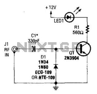
Rf Output Indicator
A simple RF detector circuit utilizing a visual indicator can serve as an RF output indicator. This circuit was designed for use as a transmitter ON indicator.
The RF detector circuit typically consists of a few key components: a diode, a...

Op-Amp Microphone Preamp
A high-quality microphone preamplifier utilizing a single power supply, suitable for both dynamic and electret microphones. The operational amplifier (op-amp) employed can be any low-noise, high-performance type, such as the NE5534, TL071, or OPA 371. The schematic illustrates the configuration...

Circuit examples
Input J4 features an offset function that is activated only when no plug is inserted into J4, as the switching contact of J4 connects to the positive supply voltage through the protection resistor R8. The inverting sum of all inputs...

How to Make a Cell Phone RF Signal Detector Circuit
A simple electronic circuit project is presented that can be constructed by any school student for display at a school science fair. The proposed circuit is a high-gain operational amplifier (op-amp) amplifier designed to detect the slightest RF disturbances generated...
op amp Humming and Transmission issues
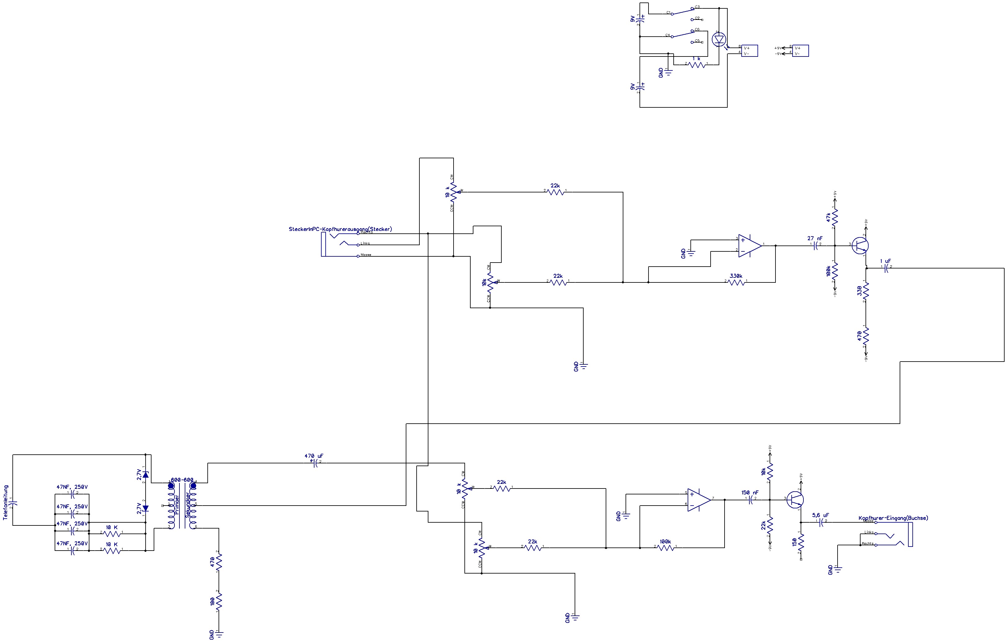
When the connection to the PC speaker is plugged in alongside the telephone connection (located at the bottom-left), a humming sound is heard in the headphones. However, when only one of the connections is used, the sound is clear without...

Triangle / Squarewave Generators
A simple triangle and square wave generator utilizing a common 1458 dual op-amp, capable of operating from very low frequencies up to approximately 10 kHz. The time interval for one half-cycle is determined by the product of resistance (R) and...

Output-limiter
The HA-5190 operational amplifier is rated for an output swing of ±5 V and saturates at ±7 V. As is typical with most operational amplifiers, the recovery time from output saturation is slower than the amplifier's normal response time. Therefore,...

Triangular Wave Generator Using Op-amp
This circuit diagram illustrates a triangular wave generating circuit utilizing a pair of operational amplifiers (Op-Amps). The LM741 Op-Amp is recommended for this application. The first Op-Amp, located on the left, functions as a comparator, while the second Op-Amp on...