


Fan Failure Detector circuit
#fan failure
#current monitoring
#transistor
#capacitor
#resistor
#DC component
#electronic commutator
#cooling system
#failure detection


Description: The cooling is not only a PC using a small fan with an electronic commutator. A special feature of these fans is that their removal is less dependent on the load. Indicators monitoring the DC component of current may therefore be very reliable. Interesting connection indicator I found in Electronic Design magazine. The indicator in Figure 1, the only change in passing current. Measured current waveform is the fan in Figure 2. The voltage at the base of the transistor is filtered by resistor R1 and capacitor C1. The immediate changes in the supply current (during the fall) opens the transistor and discharges the capacitor C2. If he stops the fan, the voltage on the base and emitter of the same transistor and remains closed. Capacitor C2 is charged and logical level H output indicates a fault. Initial involvement was not accompanied MAX6501 circuit for indicating overheating. Serial sensing resistor for the fan normal PC too little resistance. For most fans meet resistance 12 ohm. Some fans, however, show only a small ripple current. In this case, the resistor further increase. This indication may not be sufficient. Figure 5 is a circuit with a Piezo. In both cases, instead of a LED in series with the optocoupler LED engage, whose output can be linked to other devices, such as a microprocessor or a switch port back-up fan. This requires the involvement of voltage drop on the series resistor of 1 to 1.5 V. At lower supply voltage, however, reduced cooling capacity. The resistance of the serial resistors can be reduced and more transistors can be used as an amplifier AC scanned from the resistor. In practical tests, however, showed that this circuit is very sensitive to supply voltage ripple. After some experimentation, I designed the circuit in Figure 6. In the prior involvement of the transistor T1 permanently closed and opened only for a brief moment in the decline in the supply current. Conversely, the involvement of Figure 6 is permanently open to the transistor current passing through R1 and for a moment close to peak supply current. Stops - When the fan transistor will remain open permanently. A serial resistor Rs may have in this case about half the resistance for the same sensitivity. Other districts only process signals from the transistor. C2 and R3 form of short positive pulses for gate level H H1. C3 and R4 response delay circuit when the power supply. Without this circuit would be a few seconds after the fan stopped indicated. Gate H2 C4 and R5 form an oscillator with a frequency of about 2 Hz. The tone oscillator interrupt indication. The inverter is another oscillator H3 with H4. This oscillator gives the direct piezoelectric transducer. Suitable choice of feedback resistor (in my case 220 or 270 ohm) oscillator can be tuned into resonance with Piezo. The resulting tone, it is very pervasive. The circuit can find applications wherever broken fan can cause overheating. It may not be just a PC, but also a charger, source or amplifier. The PC can monitor fan resources. CPU fan tends to signal rotation and embarrassed watching it directly to computer hardware.
The circuit described serves as a monitoring and fault indication system for cooling fans used in electronic devices such as PCs, chargers, and amplifiers. The primary components include a small fan equipped with an electronic commutator, a transistor, resistors, capacitors, and a piezoelectric transducer for sound indication.
The fan operates under the principle that its removal from the circuit is less influenced by load variations, allowing for reliable monitoring of the DC current component. The current waveform is analyzed through the use of a sensing resistor, typically around 12 ohms, which may need to be adjusted based on the fan's characteristics.
In the schematic, the voltage at the base of the transistor is filtered using resistor R1 and capacitor C1. This configuration allows the transistor to respond to changes in supply current by opening and discharging capacitor C2, which charges when the fan stops, triggering a fault indication through a high logic level output.
For enhanced fault detection, the circuit incorporates a MAX6501 for overheating indication, although the initial resistance values may be insufficient for certain fan types, necessitating adjustments. The design also includes a piezo buzzer, which can be activated in place of an LED, allowing for audible alerts in case of fan failure.
The circuit's sensitivity to supply voltage ripple is noted, and adjustments to the resistor values and transistor configurations can improve performance. The incorporation of additional components such as capacitors C2, C3, and resistors R3, R4, and R5 creates a delay circuit and oscillators, which provide a consistent indication tone at a frequency of approximately 2 Hz, enhancing the alert mechanism.
This monitoring circuit is versatile and can be adapted for various applications beyond PCs, including any system where fan failure could lead to overheating, thus ensuring reliable operation and protection of electronic components.The cooling is not only a PC using a small fan with an electronic commutator [1]. A special feature of these fans is that their removal is less dependent on the load. Indicators monitoring the DC component of current may therefore be very reliable. Interesting connection indicator I found in Electronic Design magazine [2]. The indicator in Figure 1, the only change in passing current. Measured current waveform is the fan in Figure 2 The voltage at the base of the transistor is filtered by resistor R1 and capacitor C1. The immediate changes in the supply current (during the fall) opens the transistor and discharges the capacitor C2.
If he stops the fan, the voltage on the base and emitter of the same transistor and remains closed. Capacitor C2 is charged and logical level H output indicates a fault. Initial involvement was not accompanied MAX6501 circuit for indicating overheating. Serial sensing resistor for the fan normal PC too little resistance. For most fans meet resistance 12 ohm. Some fans, however, show only a small ripple current, see Figure 3 In this case, the resistor further increase. The cooling is not only a PC using a small fan with an electronic commutator [1]. A special feature of these fans is that their removal is less dependent on the load. Indicators monitoring the DC component of current may therefore be very reliable. Interesting connection indicator I found in Electronic Design magazine [2]. The indicator in Figure 1, the only change in passing current. Measured current waveform is the fan in Figure 2 The voltage at the base of the transistor is filtered by resistor R1 and capacitor C1.
The immediate changes in the supply current (during the fall) opens the transistor and discharges the capacitor C2. If he stops the fan, the voltage on the base and emitter of the same transistor and remains closed. Capacitor C2 is charged and logical level H output indicates a fault. Initial involvement was not accompanied MAX6501 circuit for indicating overheating. Serial sensing resistor for the fan normal PC too little resistance. For most fans meet resistance 12 ohm. Some fans, however, show only a small ripple current, see Figure 3 In this case, the resistor further increase.
This indication may not be sufficient. Figure 5 is a circuit with a Piezo. In both cases, instead of a LED in series with the optocoupler LED engage, whose output can be linked to other devices, such as a microprocessor or a switch port back-up fan. This requires the involvement of voltage drop on the series resistor of 1 to 1.5 V. At lower supply voltage, however, reduced cooling capacity. The resistance of the serial resistors can be reduced and more transistors can be used as an amplifier AC scanned from the resistor.
In practical tests, however, showed that this circuit is very sensitive to supply voltage ripple. After some experimentation, I designed the circuit in Figure 6 In the prior involvement of the transistor T1 permanently closed and opened only for a brief moment in the decline in the supply current. Conversely, the involvement of Figure 6 is permanently open to the transistor current passing through R1 and for a moment close to peak supply current.
Stops - When the fan transistor will remain open permanently. A serial resistor Rs may have in this case about half the resistance for the same sensitivity. Other districts only process signals from the transistor. C2 and R3 form of short positive pulses for gate level H H1. C3 and R4 response delay circuit when the power supply. Without this circuit would be a few seconds after the fan stopped indicated. Gate H2 C4 and R5 form an oscillator with a frequency of about 2 Hz. The tone oscillator interrupt indication. The inverter is another oscillator H3 with H4. This oscillator gives the direct piezoelectric transducer. Suitable choice of feedback resistor (in my case 220 or 270 ohm) oscillator can be tuned into resonance with Piezo. The resulting tone, it is very pervasive. The circuit can find applications wherever broken fan can cause overheating. It may not be just a PC, but also a charger, source or amplifier. The PC can monitor fan resources. CPU fan tends to signal rotation and embarrassed watching it directly to computer hardware.
The circuit described serves as a monitoring and fault indication system for cooling fans used in electronic devices such as PCs, chargers, and amplifiers. The primary components include a small fan equipped with an electronic commutator, a transistor, resistors, capacitors, and a piezoelectric transducer for sound indication.
The fan operates under the principle that its removal from the circuit is less influenced by load variations, allowing for reliable monitoring of the DC current component. The current waveform is analyzed through the use of a sensing resistor, typically around 12 ohms, which may need to be adjusted based on the fan's characteristics.
In the schematic, the voltage at the base of the transistor is filtered using resistor R1 and capacitor C1. This configuration allows the transistor to respond to changes in supply current by opening and discharging capacitor C2, which charges when the fan stops, triggering a fault indication through a high logic level output.
For enhanced fault detection, the circuit incorporates a MAX6501 for overheating indication, although the initial resistance values may be insufficient for certain fan types, necessitating adjustments. The design also includes a piezo buzzer, which can be activated in place of an LED, allowing for audible alerts in case of fan failure.
The circuit's sensitivity to supply voltage ripple is noted, and adjustments to the resistor values and transistor configurations can improve performance. The incorporation of additional components such as capacitors C2, C3, and resistors R3, R4, and R5 creates a delay circuit and oscillators, which provide a consistent indication tone at a frequency of approximately 2 Hz, enhancing the alert mechanism.
This monitoring circuit is versatile and can be adapted for various applications beyond PCs, including any system where fan failure could lead to overheating, thus ensuring reliable operation and protection of electronic components.The cooling is not only a PC using a small fan with an electronic commutator [1]. A special feature of these fans is that their removal is less dependent on the load. Indicators monitoring the DC component of current may therefore be very reliable. Interesting connection indicator I found in Electronic Design magazine [2]. The indicator in Figure 1, the only change in passing current. Measured current waveform is the fan in Figure 2 The voltage at the base of the transistor is filtered by resistor R1 and capacitor C1. The immediate changes in the supply current (during the fall) opens the transistor and discharges the capacitor C2.
If he stops the fan, the voltage on the base and emitter of the same transistor and remains closed. Capacitor C2 is charged and logical level H output indicates a fault. Initial involvement was not accompanied MAX6501 circuit for indicating overheating. Serial sensing resistor for the fan normal PC too little resistance. For most fans meet resistance 12 ohm. Some fans, however, show only a small ripple current, see Figure 3 In this case, the resistor further increase. The cooling is not only a PC using a small fan with an electronic commutator [1]. A special feature of these fans is that their removal is less dependent on the load. Indicators monitoring the DC component of current may therefore be very reliable. Interesting connection indicator I found in Electronic Design magazine [2]. The indicator in Figure 1, the only change in passing current. Measured current waveform is the fan in Figure 2 The voltage at the base of the transistor is filtered by resistor R1 and capacitor C1.
The immediate changes in the supply current (during the fall) opens the transistor and discharges the capacitor C2. If he stops the fan, the voltage on the base and emitter of the same transistor and remains closed. Capacitor C2 is charged and logical level H output indicates a fault. Initial involvement was not accompanied MAX6501 circuit for indicating overheating. Serial sensing resistor for the fan normal PC too little resistance. For most fans meet resistance 12 ohm. Some fans, however, show only a small ripple current, see Figure 3 In this case, the resistor further increase.
This indication may not be sufficient. Figure 5 is a circuit with a Piezo. In both cases, instead of a LED in series with the optocoupler LED engage, whose output can be linked to other devices, such as a microprocessor or a switch port back-up fan. This requires the involvement of voltage drop on the series resistor of 1 to 1.5 V. At lower supply voltage, however, reduced cooling capacity. The resistance of the serial resistors can be reduced and more transistors can be used as an amplifier AC scanned from the resistor.
In practical tests, however, showed that this circuit is very sensitive to supply voltage ripple. After some experimentation, I designed the circuit in Figure 6 In the prior involvement of the transistor T1 permanently closed and opened only for a brief moment in the decline in the supply current. Conversely, the involvement of Figure 6 is permanently open to the transistor current passing through R1 and for a moment close to peak supply current.
Stops - When the fan transistor will remain open permanently. A serial resistor Rs may have in this case about half the resistance for the same sensitivity. Other districts only process signals from the transistor. C2 and R3 form of short positive pulses for gate level H H1. C3 and R4 response delay circuit when the power supply. Without this circuit would be a few seconds after the fan stopped indicated. Gate H2 C4 and R5 form an oscillator with a frequency of about 2 Hz. The tone oscillator interrupt indication. The inverter is another oscillator H3 with H4. This oscillator gives the direct piezoelectric transducer. Suitable choice of feedback resistor (in my case 220 or 270 ohm) oscillator can be tuned into resonance with Piezo. The resulting tone, it is very pervasive. The circuit can find applications wherever broken fan can cause overheating. It may not be just a PC, but also a charger, source or amplifier. The PC can monitor fan resources. CPU fan tends to signal rotation and embarrassed watching it directly to computer hardware.

audio tone control 2 transistor circuit
The first BC109C transistor functions as a buffer, delivering a high input impedance of approximately 250k and exhibiting a voltage gain marginally below unity. Given that the Baxendall tone control circuit operates passively, it attenuates all audio frequencies. The audio...

modified battery charger circuit
Using a transistor will not yield accurate results, and the adjustment process can become quite tedious. The circuit is technically correct; if the tripping point can be adjusted properly, it may function as intended. Vinod states that he created a...
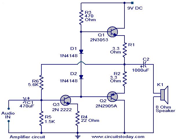
Low Cost Amplifier Circuit Using Three Transistors
The operation and circuit diagram of a low-cost amplifier utilizing BC107 and BC148 transistors are explained in detail.
The low-cost amplifier circuit employs two types of transistors, BC107 and BC148, which are commonly used for their favorable characteristics in audio amplification...

A Transistor Based Motorcycle Alarm circuit
This circuit includes a timed output and an automatic reset feature. It can be manually operated using a key switch or a concealed switch. By incorporating an external relay, the circuit will automatically engage or immobilize the machine each time...
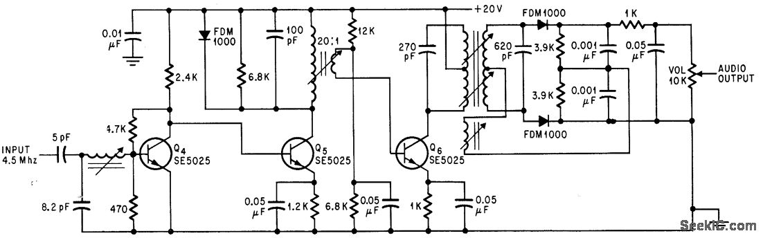
SOUND I F FOR COLOR TV
Utilizes three transistor stages and a Foster-Seeley discriminator to produce an audio output of 1 V peak-to-peak. -D. Bray, Solid State Makes Debut in Big Screen Color TV, Electronics, 39:8, p 99-105.
The circuit in question employs a combination of three...

Inverter Circuit For Soldering Iron circuit
This is a simple and cost-effective inverter designed to power a small soldering iron (25W, 35W, etc.) when a mains supply is not available. The circuit utilizes eight transistors along with several resistors and capacitors. Transistors Q1 and Q2, both...
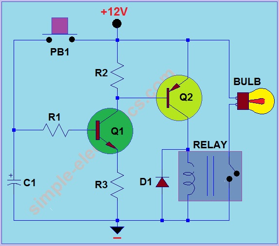
Car Headlight with Delay Circuit
This circuit operates by activating a headlight when the push-button PB1 is pressed. The headlight remains illuminated for a predetermined duration, which can range from several seconds to minutes, before automatically turning off. When PB1 is engaged, capacitor C1 begins...

Mains undervoltage overvoltage protection circuit
The circuit employs a transistor control mechanism. When the grid voltage is within the normal range, relay KA is activated, supplying power to the load. If the grid voltage falls below the minimum allowable threshold (adjustable via potentiometer RPz) or...

Direct Coupled Discrete Astable Multivibrator circuit
This flip-flop circuit functions as a free-running astable multivibrator, where the bases and collectors of both emitter-biased transistors are directly coupled. The switching action is facilitated by a capacitor in each emitter circuit, resulting in the generation of triangle waves...