


Fluid Level Detector Circuit PCB
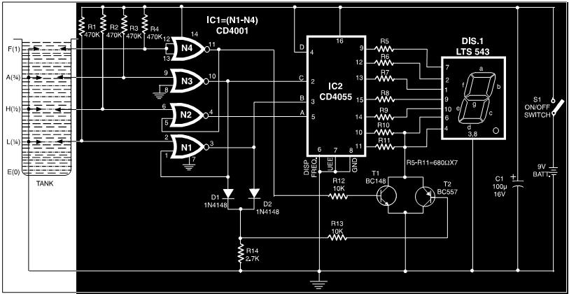
Description: This circuit is a fluid level indicator that displays each level using meaningful English letters. It employs a seven-segment display to represent the letters E for empty, L for low, H for half, A for above average, and F for full tank. The circuit consists of CMOS ICs CD4001, CD4055, and a seven-segment display driver. The decoder IC is designed to display English letters in addition to the standard digits 0 through 9 for indicating fluid levels. The BCD codes for the various displays are provided in a table. The use of CMOS ICs results in extremely low current consumption, allowing the circuit to be powered by a battery.
The fluid level indicator circuit is designed to provide a clear and intuitive representation of liquid levels in a tank or reservoir. The seven-segment display is utilized to show five distinct states of fluid levels, enhancing user understanding through the use of recognizable letters. The letters displayed correspond to specific fluid levels: 'E' indicates an empty tank, 'L' signifies a low level, 'H' represents a half-full condition, 'A' denotes an above-average level, and 'F' indicates a full tank.
The core of the circuit is based on two CMOS ICs: the CD4001, which is a quad 2-input NAND gate, and the CD4055, which functions as a BCD to seven-segment decoder/driver. The CD4001 is used for logical operations that determine the current fluid level based on input from sensors placed at different heights within the tank. These sensors can be float switches or conductive probes that detect the presence or absence of liquid.
The CD4055 takes the binary-coded decimal (BCD) input from the logic gates and converts it into a format suitable for driving the seven-segment display. This IC is particularly advantageous due to its ability to handle both numerical and alphabetic outputs, making it ideal for this application. The BCD codes needed to display the letters are specified in a reference table, which maps the input signals to the corresponding outputs on the display.
Power efficiency is a crucial aspect of this circuit. The use of CMOS technology ensures that the circuit consumes minimal current, which is especially beneficial for battery-operated devices. This low power requirement allows the fluid level indicator to operate for extended periods without the need for frequent battery replacements, enhancing its practicality in various applications.
In summary, this fluid level indicator circuit provides a user-friendly method for monitoring liquid levels, utilizing a combination of CMOS technology and a seven-segment display to convey information clearly and efficiently. The design is suitable for various applications where fluid level monitoring is essential, including water tanks, chemical reservoirs, and other liquid storage systems.Here is the circuit of a fluid level indicator which shows each level in meaningful English letters. The circuit presented here using seven segment display to display the letter E for empty, L for low, H for half, A for above average, and F for full tank. The circuit is comprised of CMOS IC`s CD4001, CD4055 and a 7 segment display driver. The dec oder IC is capable of displaying the English letters besides the usual digits 0 through 9 to disply fluid levels. The BCD codes for various displays are given in Table. The CMOS IC`s make current consumption extremely low so we can power the circuit from a battery.
The fluid level indicator circuit is designed to provide a clear and intuitive representation of liquid levels in a tank or reservoir. The seven-segment display is utilized to show five distinct states of fluid levels, enhancing user understanding through the use of recognizable letters. The letters displayed correspond to specific fluid levels: 'E' indicates an empty tank, 'L' signifies a low level, 'H' represents a half-full condition, 'A' denotes an above-average level, and 'F' indicates a full tank.
The core of the circuit is based on two CMOS ICs: the CD4001, which is a quad 2-input NAND gate, and the CD4055, which functions as a BCD to seven-segment decoder/driver. The CD4001 is used for logical operations that determine the current fluid level based on input from sensors placed at different heights within the tank. These sensors can be float switches or conductive probes that detect the presence or absence of liquid.
The CD4055 takes the binary-coded decimal (BCD) input from the logic gates and converts it into a format suitable for driving the seven-segment display. This IC is particularly advantageous due to its ability to handle both numerical and alphabetic outputs, making it ideal for this application. The BCD codes needed to display the letters are specified in a reference table, which maps the input signals to the corresponding outputs on the display.
Power efficiency is a crucial aspect of this circuit. The use of CMOS technology ensures that the circuit consumes minimal current, which is especially beneficial for battery-operated devices. This low power requirement allows the fluid level indicator to operate for extended periods without the need for frequent battery replacements, enhancing its practicality in various applications.
In summary, this fluid level indicator circuit provides a user-friendly method for monitoring liquid levels, utilizing a combination of CMOS technology and a seven-segment display to convey information clearly and efficiently. The design is suitable for various applications where fluid level monitoring is essential, including water tanks, chemical reservoirs, and other liquid storage systems.Here is the circuit of a fluid level indicator which shows each level in meaningful English letters. The circuit presented here using seven segment display to display the letter E for empty, L for low, H for half, A for above average, and F for full tank. The circuit is comprised of CMOS IC`s CD4001, CD4055 and a 7 segment display driver. The dec oder IC is capable of displaying the English letters besides the usual digits 0 through 9 to disply fluid levels. The BCD codes for various displays are given in Table. The CMOS IC`s make current consumption extremely low so we can power the circuit from a battery.

Removing pop from a CMOS switch
A simple audio switching circuit is experiencing issues. The circuit utilizes a CD40106 Schmitt Trigger in conjunction with a CD4066 CMOS switch to route audio signals.
The circuit design incorporates a CD40106 Schmitt Trigger, which is essential for providing clean signal...

Quiz Circuit
This design utilizes four integrated circuits (ICs) and features four input circuits with four independent outputs, along with a single master reset switch. The outputs are configured with light-emitting diodes (LEDs), which can be modified to control lamps or buzzers....
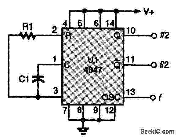
CD4047 CMOS OSCILLATOR
This CMOS square-wave oscillator utilizes the 4047 multivibrator circuit, suitable for both monostable (one-shot) and astable applications. In the provided configuration, the 4047 operates as an astable multivibrator. The circuit features three outputs from the 4047, with the first being...

Optical-cmos-coupler
Standard CMOS logic operates with supply voltages as low as 3 V and is specified for a maximum current sinking/sourcing capability of 30 pA. To drive the infrared emitting diode (IRED) when utilizing CMOS to control an optocoupler, it is...
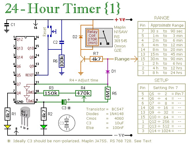
two cmos based 24 hour timers
A pair of multi-range timers capable of timing periods up to 24 hours and beyond. Both versions are fundamentally similar, with the primary distinction being that Version 1 energizes the relay when the time expires, while Version 2 de-energizes it....

Gate automatic lamp circuit
The circuit utilizes multiple integrated circuits to form an automatic lighting device that is activated by door and window sensors. It includes CD4093 digital integrated circuits, a relay, and a power supply circuit. The system typically remains closed when a...
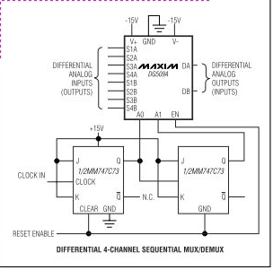
DG509A Schematic for Monolithic Cmos Analog Multiplexers
Maxim's DG508A and DG509A are monolithic CMOS analog multiplexers. The DG508A is a single 8-channel (1-of-8) multiplexer, while the DG509A is a differential 4-channel (2-of-8) multiplexer. Both devices guarantee high performance and reliability.
The DG508A and DG509A analog multiplexers are designed...

CD4001 composed of single-channel modulator
The core elements of this circuit are the second four-input NOR gate terminal IC CD4001. The entire circuit features a simple structure, with fewer components, making it easy to construct, particularly for remote control transmitters or carrier modulation transmission. The...

4081 AND gates
The inputs of the gate must be connected to either LOW or HIGH and must not be left open circuit. This is achieved through the use of input switches along with their pull-down resistors. To prevent loading on the gate's...