


Fluid Level Sensor
#fluid level sensor
#AC-sensing
#relay
#stainless steel probes
#corrosion prevention
#MC14093B
#2N3906
#1N4001
#1N4148

Description: R1 = 470K, N1, N2 = MC14093B, R2 = 15M, T1 = 2N3906 (also compatible: PN200, 2N4413), C1-C4 = 2.2nF (NTE159, ECG159, BC557, BC157, TUP), D1 = 1N4001, Ry = Relay (12V or matching supply voltage), D2, D3 = 1N4148. Sensor = Stainless steel probes, brass, chrome, etc. The circuit utilizes an AC-sensing signal to prevent electrolytic corrosion on the probes. The AC signal is rectified to drive transistor T1, which in turn operates the relay. The relay should be a 12V type. Diodes D2 and D3 are small signal diodes (1N4148), while diode D1 (1N4001) protects against transients and sparking across the relay coil. It is recommended to use a rectifier diode like the 1N4001 instead of a signal diode. The MC14093B is a CMOS quad 2-input NAND Schmitt trigger with a supply voltage range of 3.0 to 18V DC and is pin-compatible with the CD4093. The capacitors are standard ceramic types, but alternatives may be used. Unused inputs must be connected to a suitable voltage level, either ground or +12V, specifically tying pins 8, 9, 12, and 13 accordingly. Unused outputs (10 & 11) should be left open for potential future use. Regarding the sensor, stainless steel is preferred, though other materials may be explored. The choice of sensor material should be based on the fluid type to ensure corrosion resistance. The sensor operates primarily through resistive conduction, detecting lowered resistance in the fluid rather than increased capacitance. For insulating fluids, the circuit could potentially detect capacitance changes, but this requires careful configuration. Additionally, multiple resistive sensors can be connected in parallel to monitor fluid levels at various locations.
The circuit described functions as a fluid level detection system that mitigates electrolytic corrosion through the use of stainless steel or similar probes. The primary components include a quad 2-input NAND Schmitt trigger (MC14093B), a transistor (2N3906), and a relay that operates at 12V. The circuit is designed to rectify an AC signal, which is essential for driving the transistor, allowing it to control the relay based on the fluid level detected by the sensor.
The MC14093B plays a critical role in processing the input signals. It features a supply voltage range of 3.0 to 18V DC, which allows for flexibility in power supply options. The configuration of unused inputs and outputs is crucial for ensuring the stability and functionality of the circuit. Properly tying unused inputs to ground or the supply voltage prevents floating states that could lead to erratic behavior.
The sensor's operation is primarily based on resistive conduction, which is effective in fluids that are not perfect insulators, such as water. This property allows the circuit to detect fluid presence by measuring the change in resistance as the fluid replaces air in the sensor's gap. For applications involving insulating fluids, a capacitive detection method could be implemented, but it requires careful design considerations, including the size of the sensor plates and the distance between them.
The diodes in the circuit serve specific protective roles. The 1N4001 diode safeguards against voltage spikes when the relay coil is energized, while the 1N4148 diodes are used for signal processing. The relay chosen must be compatible with the supply voltage and capable of handling the load requirements of the application.
This circuit can be utilized in various applications, including monitoring sewer line plugs, detecting leaks from hot water heaters, and overseeing condensate pump operations. Its versatility and functionality make it suitable for both residential and industrial uses, provided that the sensor materials are chosen based on the specific fluids being monitored.R1 = 470K N1, N2 = MC14093B R2 = 15M* T1 = 2N3906 (these will work also: PN200, 2N4413) C1-C4 = 2N2 (2. 2nF) (NTE159, ECG159, BC557, BC157, TUP ) D1 = 1N4001 Ry = Relay (12V or matching supply voltage) D2, 3 = 1N4148 Sensor = Stainless Steel probes, brass, chrome, etc.
The above circuit uses an AC-sensing signal to eliminate electrolytic corrosion on the probes. The AC signal is rectified and used to drive Transistor T1 that drives the relay. The relay is a 12-V type of your choice. Diodes D2 and D3 are both small signal diodes (1N4148). Diode D1 (1N4001) eliminates transients and possible sparking over the relay coil. Do not use a signal diode for this but a rectifier diode like the 1N4001 or other types of the 1N400x series. The MC14093B is a CMOS quad 2-input NAND Schmitt trigger. The supply voltage can be between 3. 0 and 18Vdc. It is pin-for-pin compatible with the CD4093. The capacitors are standard ceramic types but try others if you have them available. Please note: UnusedinputsMUSTbe tied to an appropriate voltage level, either ground or +12V. In this case, tie input pins 8, 9, 12, and 13 to either ground or +12v. Unusedoutputs (10 & 11)MUSTbe left open. You can use them as spares when needed. In regards to the sensor, use your imagination. Stainless steel would be preferred but try other materials too. Depending on what type of fluid you use it for you naturally would choose your type of sensor which would resist corrosion for that particular fluid.
I often use chrome bicycle spokes with very good success. The `Sensor` works via the capacitive method. Thanks, Tony, for publishing your Fluid-Level Sensor design. I`m using it to detect sewer line plugs (water backing up toward the access port), and hot water heater / clothes washer / AC condensate pump overflows/leaks (water on the basement floor). It works very well. Also, it says "the `Sensor` works via the capacitive method. " But I don`t think that is correct. It would be more accurate to say that, for detecting fluids that are perfect insulators, the circuit CAN be made to work by detecting an increase in capacitance when the fluid replaces air in an air gap in the sensor.
But for the more common case of fluids that are not perfect insulators (like water on my basement floor), the circuit works by detecting resistive conduction through the fluid. It is lowered resistance that is detected, not increased capacitance. To detect insulating fluids via the capacitive method would require good sized plates separated by an air gap, and careful adjustment of the sensitivity via R2 to distinguish between the possibly small change in capacitance due to the presence of the fluid.
The difference might be small because there is only a fairly small differences between the dielectric constants of air and some common fluids. E. g. , air has a dielectric constant of 1, and typical oils have dielectric constants of 2 to 5. Note, too, that desire to get a measurably large amount of capacitance leads us to desire that the gap between the plates be small (because the capacitance is inversely proportional to the distance between the plates), but the gap cannot be too small, lest capillary action hold fluid between the plates even after the fluid level has dropped below our sensor.
Also, one handy feature not mentioned in the article is that several resistive "sensors" can be hooked up together (in parallel) to detect fluid at any of several different locations.
The circuit described functions as a fluid level detection system that mitigates electrolytic corrosion through the use of stainless steel or similar probes. The primary components include a quad 2-input NAND Schmitt trigger (MC14093B), a transistor (2N3906), and a relay that operates at 12V. The circuit is designed to rectify an AC signal, which is essential for driving the transistor, allowing it to control the relay based on the fluid level detected by the sensor.
The MC14093B plays a critical role in processing the input signals. It features a supply voltage range of 3.0 to 18V DC, which allows for flexibility in power supply options. The configuration of unused inputs and outputs is crucial for ensuring the stability and functionality of the circuit. Properly tying unused inputs to ground or the supply voltage prevents floating states that could lead to erratic behavior.
The sensor's operation is primarily based on resistive conduction, which is effective in fluids that are not perfect insulators, such as water. This property allows the circuit to detect fluid presence by measuring the change in resistance as the fluid replaces air in the sensor's gap. For applications involving insulating fluids, a capacitive detection method could be implemented, but it requires careful design considerations, including the size of the sensor plates and the distance between them.
The diodes in the circuit serve specific protective roles. The 1N4001 diode safeguards against voltage spikes when the relay coil is energized, while the 1N4148 diodes are used for signal processing. The relay chosen must be compatible with the supply voltage and capable of handling the load requirements of the application.
This circuit can be utilized in various applications, including monitoring sewer line plugs, detecting leaks from hot water heaters, and overseeing condensate pump operations. Its versatility and functionality make it suitable for both residential and industrial uses, provided that the sensor materials are chosen based on the specific fluids being monitored.R1 = 470K N1, N2 = MC14093B R2 = 15M* T1 = 2N3906 (these will work also: PN200, 2N4413) C1-C4 = 2N2 (2. 2nF) (NTE159, ECG159, BC557, BC157, TUP ) D1 = 1N4001 Ry = Relay (12V or matching supply voltage) D2, 3 = 1N4148 Sensor = Stainless Steel probes, brass, chrome, etc.
The above circuit uses an AC-sensing signal to eliminate electrolytic corrosion on the probes. The AC signal is rectified and used to drive Transistor T1 that drives the relay. The relay is a 12-V type of your choice. Diodes D2 and D3 are both small signal diodes (1N4148). Diode D1 (1N4001) eliminates transients and possible sparking over the relay coil. Do not use a signal diode for this but a rectifier diode like the 1N4001 or other types of the 1N400x series. The MC14093B is a CMOS quad 2-input NAND Schmitt trigger. The supply voltage can be between 3. 0 and 18Vdc. It is pin-for-pin compatible with the CD4093. The capacitors are standard ceramic types but try others if you have them available. Please note: UnusedinputsMUSTbe tied to an appropriate voltage level, either ground or +12V. In this case, tie input pins 8, 9, 12, and 13 to either ground or +12v. Unusedoutputs (10 & 11)MUSTbe left open. You can use them as spares when needed. In regards to the sensor, use your imagination. Stainless steel would be preferred but try other materials too. Depending on what type of fluid you use it for you naturally would choose your type of sensor which would resist corrosion for that particular fluid.
I often use chrome bicycle spokes with very good success. The `Sensor` works via the capacitive method. Thanks, Tony, for publishing your Fluid-Level Sensor design. I`m using it to detect sewer line plugs (water backing up toward the access port), and hot water heater / clothes washer / AC condensate pump overflows/leaks (water on the basement floor). It works very well. Also, it says "the `Sensor` works via the capacitive method. " But I don`t think that is correct. It would be more accurate to say that, for detecting fluids that are perfect insulators, the circuit CAN be made to work by detecting an increase in capacitance when the fluid replaces air in an air gap in the sensor.
But for the more common case of fluids that are not perfect insulators (like water on my basement floor), the circuit works by detecting resistive conduction through the fluid. It is lowered resistance that is detected, not increased capacitance. To detect insulating fluids via the capacitive method would require good sized plates separated by an air gap, and careful adjustment of the sensitivity via R2 to distinguish between the possibly small change in capacitance due to the presence of the fluid.
The difference might be small because there is only a fairly small differences between the dielectric constants of air and some common fluids. E. g. , air has a dielectric constant of 1, and typical oils have dielectric constants of 2 to 5. Note, too, that desire to get a measurably large amount of capacitance leads us to desire that the gap between the plates be small (because the capacitance is inversely proportional to the distance between the plates), but the gap cannot be too small, lest capillary action hold fluid between the plates even after the fluid level has dropped below our sensor.
Also, one handy feature not mentioned in the article is that several resistive "sensors" can be hooked up together (in parallel) to detect fluid at any of several different locations.

Lantern making use of a relay control circuit
220V mains electricity is sent through a 0.33 µF capacitor (Ci) and a 50 kΩ resistive drop. A bridge rectifier composed of diodes D1 to D4 converts the AC voltage to DC. After passing through a 100 µF capacitor for...

Relay type starting circuit diagram
The figure below illustrates the use of a relay in the starting circuit. The power input connects through a resistor R, which serves two purposes: first, it prevents a large current from the capacitor C1 from affecting the power supply...

Control Circuits
This low current relay circuit is designed for use in battery-operated electronic devices. Its operating current is in microamperes (µA). This is achieved by using a bistable relay and incorporating additional components to enable the relay to function like a...

1N4001 Diodes
This article outlines various audiophile projects, including the DDDAC 2000, and discusses components such as the 1N4001 diode. The content is straightforward and informative, providing insights into these projects. For instance, readers can find and purchase the 1N4001 diode through...

5-Volt RelayCircuit for Controlling AC Current
The schematic illustrates the Relay Wiring Circuit Diagram used to control an air conditioner or other high-current devices via a microcontroller.
The relay wiring circuit serves as an interface between low-voltage microcontroller signals and high-voltage appliances, such as air conditioners. This...

Two Simple Relay Based Motorcycle Alarms
Two simple relay-based motorcycle alarm circuits. These are easy to build and can be used to protect motorcycles, but they also have many other applications. If relays with 6-volt coils are used...
The motorcycle alarm circuits described consist of two basic...

Relay Sequencer Board
A relay sequencer is utilized in a radio transverter to activate specific stages sequentially after a brief delay. This project outlines the construction of this sequencer, which features a stage that switches the output/input of the driving radio to the...
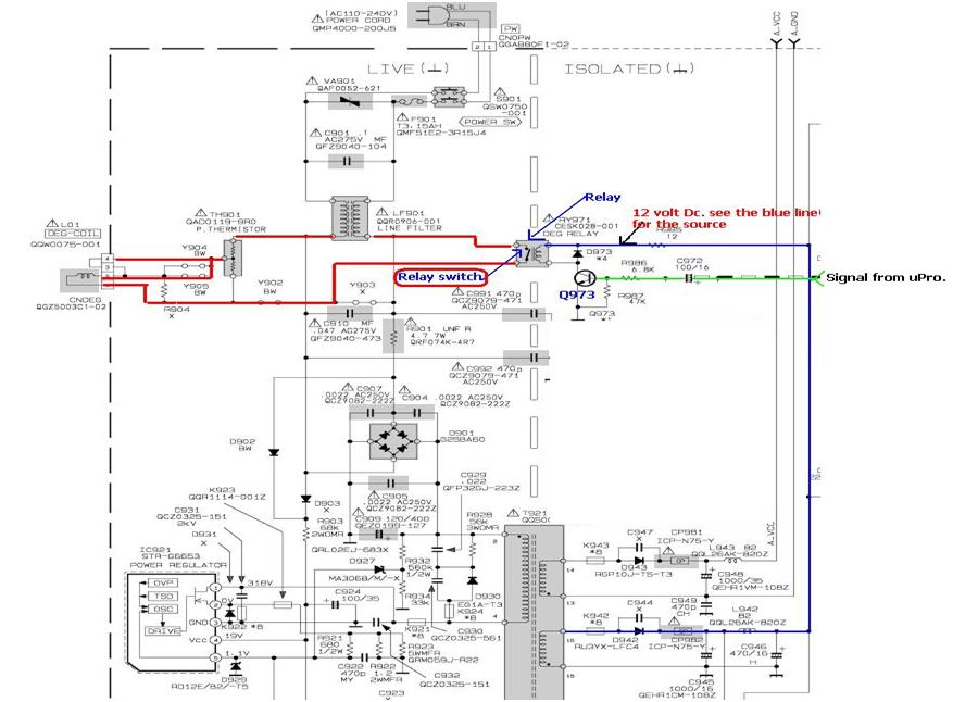
relay found in switch mode power supply
In the example above, a low voltage (12V DC) is utilized to activate a relay that switches a 240V AC main circuit. It is important to note that there is no electrical connection between the two circuits within the relay;...

simple fluid level sensor circuit
This compact single-chip circuit is designed for measuring the level of electrically conductive fluids or liquids. It functions as a voltage level sensor and employs an AC bias supply to prevent electrolysis of the probes, thereby enhancing their lifespan. This...