


Gamma-Photon Radiation Detector
#PIN photodiode
#low-noise op amps
#comparator
#gamma radiation
#photon detection
#radiation detector
#sensor circuit
#op amp circuit
#signal processing
#component selection

Description: A PIN photodiode, four low-noise operational amplifiers, and a comparator are utilized to detect individual photons of gamma radiation. The schematic, design considerations, and component selection are discussed.
The circuit design incorporates a PIN photodiode, which is a semiconductor device that converts light into an electrical current. When exposed to gamma radiation, the photodiode generates a measurable photocurrent proportional to the intensity of the incoming photons. The low-noise operational amplifiers are essential for amplifying the small signals produced by the photodiode. Their low noise characteristics ensure that the system can detect even the faintest signals without significant interference from background noise.
The output from the photodiode is fed into the first operational amplifier, which is configured in a transimpedance amplifier configuration. This setup converts the photocurrent into a voltage signal, allowing for easier processing. Following this, the signal is passed through additional low-noise operational amplifiers to further amplify the voltage while maintaining signal integrity.
The comparator is employed to determine whether the amplified signal exceeds a predefined threshold, indicating the presence of a photon. This threshold can be adjusted based on the specific application requirements, allowing for flexibility in detection sensitivity. The output of the comparator can be used to trigger additional circuits or systems, such as a digital readout or data acquisition system.
In summary, the circuit is designed to provide a reliable and sensitive method for detecting individual photons of gamma radiation, leveraging the properties of the PIN photodiode and low-noise operational amplifiers, along with a comparator for signal processing. The careful selection and arrangement of components are crucial for optimizing performance and ensuring accurate detection in various applications, including medical imaging, radiation monitoring, and scientific research.A PIN photodiode, four low-noise op amps and a comparator are used to detect individual photons of gamma radiation. The schematic, design considerations and component selection are discussed..
The circuit design incorporates a PIN photodiode, which is a semiconductor device that converts light into an electrical current. When exposed to gamma radiation, the photodiode generates a measurable photocurrent proportional to the intensity of the incoming photons. The low-noise operational amplifiers are essential for amplifying the small signals produced by the photodiode. Their low noise characteristics ensure that the system can detect even the faintest signals without significant interference from background noise.
The output from the photodiode is fed into the first operational amplifier, which is configured in a transimpedance amplifier configuration. This setup converts the photocurrent into a voltage signal, allowing for easier processing. Following this, the signal is passed through additional low-noise operational amplifiers to further amplify the voltage while maintaining signal integrity.
The comparator is employed to determine whether the amplified signal exceeds a predefined threshold, indicating the presence of a photon. This threshold can be adjusted based on the specific application requirements, allowing for flexibility in detection sensitivity. The output of the comparator can be used to trigger additional circuits or systems, such as a digital readout or data acquisition system.
In summary, the circuit is designed to provide a reliable and sensitive method for detecting individual photons of gamma radiation, leveraging the properties of the PIN photodiode and low-noise operational amplifiers, along with a comparator for signal processing. The careful selection and arrangement of components are crucial for optimizing performance and ensuring accurate detection in various applications, including medical imaging, radiation monitoring, and scientific research.A PIN photodiode, four low-noise op amps and a comparator are used to detect individual photons of gamma radiation. The schematic, design considerations and component selection are discussed..
%2Busing%2Bop%2Bamp%2B741%2Bic%2B.png "Zero Crossing Detector ZCD Comparator circuit using 741 op amp circuit")
Zero Crossing Detector (ZCD): Comparator circuit using 741 op amp
A zero crossing detector (ZCD) is a voltage comparator that switches its output between +Vsat and -Vsat (where Vsat is the saturation voltage, approximately 14V) when the input crosses the zero reference voltage. Comparators are fundamental operational amplifier circuits that...

Radiation Detector and Meter DT-590A/PDR-56F Scintillation Probe
This PDF file presents the schematic diagram of a custom-built circuit designed to drive the PDR-56 probe. A JKL BXA-12579 inverter, typically used for powering cold-cathode fluorescent lamps, serves as the high-voltage power supply. The BXA-12579 generates 1,500 VAC RMS...

Suppress Jitter With Hysteresis Circuit
When the comparator's output transitions from low to high, the rising edge of the output pulse, differentiated by the Cl/Rl chain, activates Ql. This action blocks the comparator via its strobing input and maintains its output state for a duration...
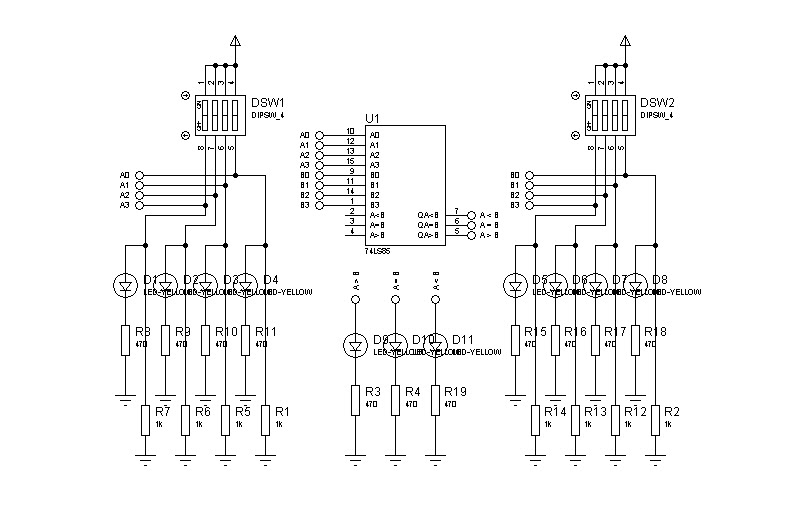
simple magnitude comparator
In designing a logic circuit, it is often necessary to compare the values of two digital data inputs. Creating a custom magnitude comparator can lead to increased use of logic integrated circuits (ICs), as well as greater time and cost...

Hi-Low level comparator
The voltage to be compared is fed through diodes D1 and D2 to the voltage dividers R1 and R5, where the low and high limits are established. When the input signal voltage exceeds the high threshold limit set with potentiometer...

The reference voltage of the symmetrical bipolar comparator
An AI comparator input is connected to a reference resistor (Rl). When the output reaches a specified level, known as VREP (absolute value), the output also stabilizes at this level. The outputs Ai and As are connected to an OR...
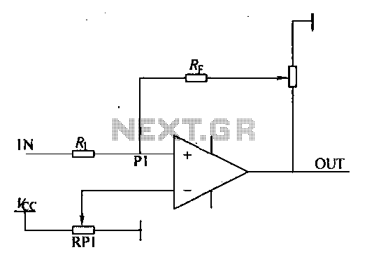
Loop comparator circuit
Environmental interference can affect the transfer switching, leading to the production of burrs in confidence disgrace. The switch position signal will control the computer system with the reliability of lanthanum burrs. The work has some impact. Glitches are typically addressed...

Micropower radioactive radiation detector
In the absence of radiation, no current is drawn. At normal background radiation levels, the power consumption is extremely low. The instrument may be left on for several months without changing batteries. In this way, the detector is always ready...

Window comparator
This circuit produces an output of 0V when the input voltage is within a specified range defined by two reference voltages. When the input voltage falls outside this range, the output becomes positive. Two operational amplifiers (op-amps) function as voltage...