


Heart Monitor (ECG Sensor Signal Amplifier/Conditioner)
#ECG
#heart monitor
#signal amplifier
#medical
#biomedical
#patient monitoring
#healthcare
#sensor conditioning
#analog circuit
#pulse detection

Description: The circuit illustrated in the schematic diagram below is designed to monitor the heart pulses of a patient. This circuit buffers and amplifies the heart pulses.
The heart pulse monitoring circuit typically consists of several key components that work together to accurately detect and amplify the electrical signals generated by the heart. The primary components include:
1. **Electrodes**: These are placed on the patient's skin to detect the electrical activity of the heart. Common configurations include a pair of electrodes placed on the chest or limbs.
2. **Buffer Amplifier**: The initial stage of the circuit is usually a buffer amplifier. This component is essential for isolating the electrodes from the subsequent amplification stages, preventing loading effects that could distort the signal. Operational amplifiers (op-amps) configured as voltage followers are commonly used for this purpose.
3. **Gain Stage**: Following the buffer, a gain stage amplifies the weak electrical signals detected by the electrodes. This stage typically involves one or more op-amps configured to provide a significant gain, often adjustable based on the specific requirements of the monitoring application.
4. **Filtering**: To ensure that only the relevant heart signal frequencies are processed, the circuit may include a filtering stage. This stage can utilize passive filters (resistors, capacitors) or active filters (using op-amps) to eliminate noise and interference from other electrical signals.
5. **Output Stage**: The final stage of the circuit is designed to present the amplified and filtered signal in a usable format. This could involve further amplification for driving a display, an analog-to-digital converter for digital output, or a wireless transmitter for remote monitoring.
6. **Power Supply**: The circuit requires a stable power supply to ensure consistent operation. Battery power is often preferred for portability, while regulated power supplies may be used in stationary applications.
This heart pulse monitoring circuit is crucial for various medical applications, including real-time patient monitoring in hospitals and remote health tracking for individuals. Proper design considerations, such as component selection and circuit layout, are vital to ensure accurate and reliable performance.Using the circuit depicted in the schematic diagram below we can monitor the heart pulses of patient. This circuit buffer and amplify the heart pulses, and the..
The heart pulse monitoring circuit typically consists of several key components that work together to accurately detect and amplify the electrical signals generated by the heart. The primary components include:
1. **Electrodes**: These are placed on the patient's skin to detect the electrical activity of the heart. Common configurations include a pair of electrodes placed on the chest or limbs.
2. **Buffer Amplifier**: The initial stage of the circuit is usually a buffer amplifier. This component is essential for isolating the electrodes from the subsequent amplification stages, preventing loading effects that could distort the signal. Operational amplifiers (op-amps) configured as voltage followers are commonly used for this purpose.
3. **Gain Stage**: Following the buffer, a gain stage amplifies the weak electrical signals detected by the electrodes. This stage typically involves one or more op-amps configured to provide a significant gain, often adjustable based on the specific requirements of the monitoring application.
4. **Filtering**: To ensure that only the relevant heart signal frequencies are processed, the circuit may include a filtering stage. This stage can utilize passive filters (resistors, capacitors) or active filters (using op-amps) to eliminate noise and interference from other electrical signals.
5. **Output Stage**: The final stage of the circuit is designed to present the amplified and filtered signal in a usable format. This could involve further amplification for driving a display, an analog-to-digital converter for digital output, or a wireless transmitter for remote monitoring.
6. **Power Supply**: The circuit requires a stable power supply to ensure consistent operation. Battery power is often preferred for portability, while regulated power supplies may be used in stationary applications.
This heart pulse monitoring circuit is crucial for various medical applications, including real-time patient monitoring in hospitals and remote health tracking for individuals. Proper design considerations, such as component selection and circuit layout, are vital to ensure accurate and reliable performance.Using the circuit depicted in the schematic diagram below we can monitor the heart pulses of patient. This circuit buffer and amplify the heart pulses, and the..

Signal Amplifier with 2N2222
A small signal amplifier, perhaps of the type to follow the previous buffer amplifier. We will assume we are buffering and amplifying our signal from the voltage controlled oscillator tutorial. In those examples we were generating and buffering 1.8 to...

Medical treat ventilator controller
The medical ventilator controller circuit consists of an astable oscillator, a control circuit, and a power supply circuit. The astable oscillator is constructed using resistors R1, R2, a potentiometer RP, capacitors C1, C2, and a time base integrated circuit IC1....

Missing-pulse-detector
This circuit detects a missing pulse or an abnormally long interval between consecutive pulses in a pulse train. The timer is configured in monostable mode, with the time delay set slightly longer than the duration of the input pulses. The...

ECG telemetry circuit diagram
The circuit is designed for teaching demonstrations or experiments to hear the electrocardiogram (ECG) signal voltage. The ECG signal voltage is amplified by the LM4250 operational amplifier, which is connected to a voltage-controlled oscillator (NE566) to modulate the oscillator output....

DIY ECG Machine On The Cheap
The purpose of an electrocardiograph (ECG) is to amplify, measure, and record the natural electrical potential generated by the heart. It is important to note that cardiac electrical signals are distinct from heart sounds, which are detected using a stethoscope....

Medical instrument preamplifier
Input current (from sensors connected to the patient) is limited to less than 5 µA under fault conditions. Note that Avol = 25 single Ni-cad battery operation.
The circuit is designed to ensure that the input current from patient-connected sensors remains...
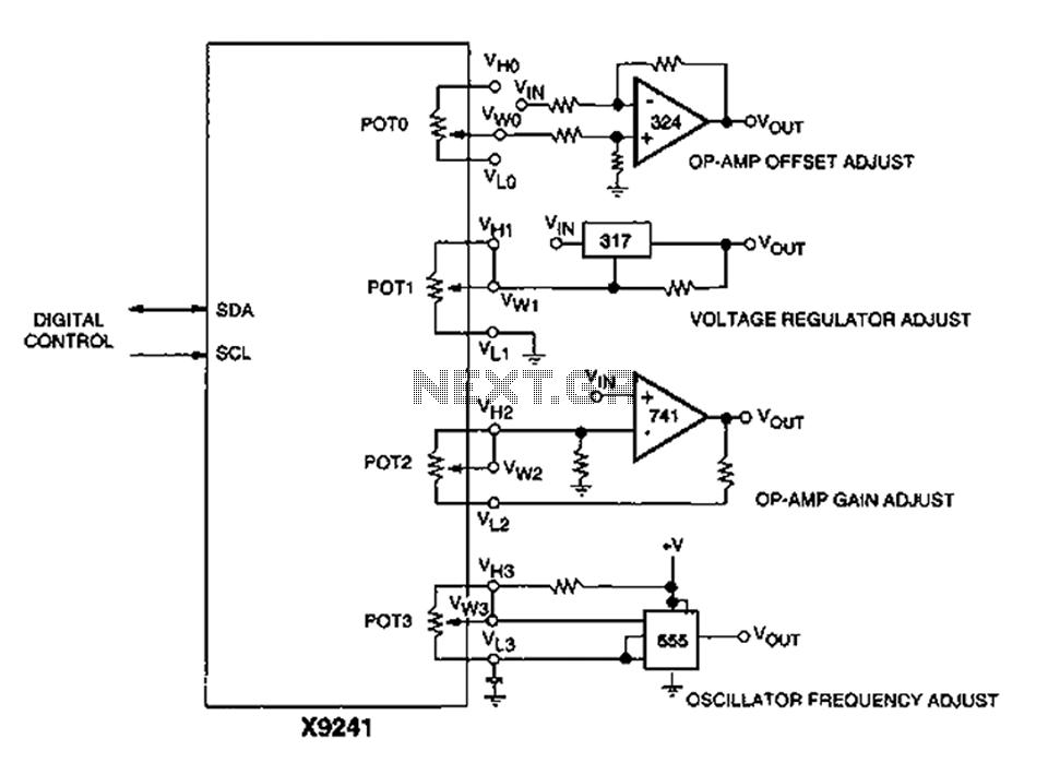
Corrector circuit diagram of an analog circuit
A XICOR X9241 POT IC module can be utilized to modify the four digital analog circuits, as depicted in the schematic.
The XICOR X9241 is a digital potentiometer integrated circuit designed for precise adjustment of analog signal levels in various electronic...
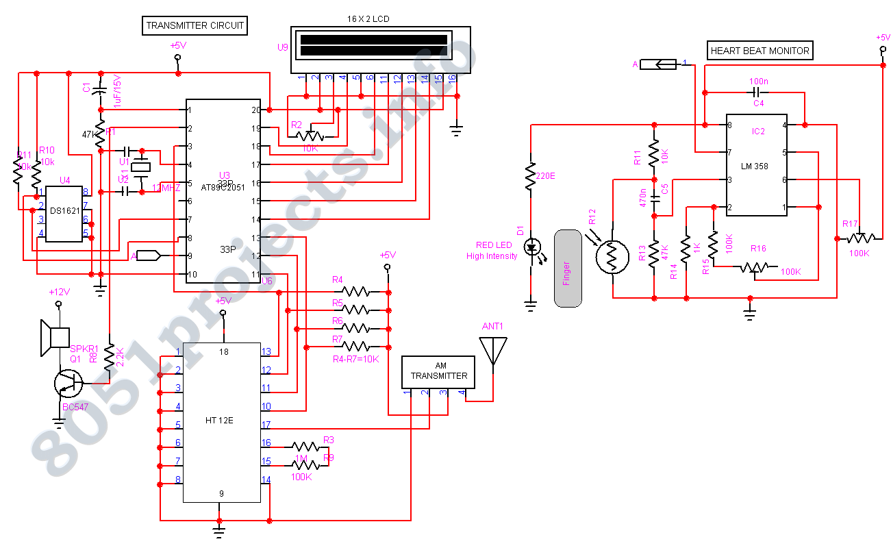
Biomedical Monitoring circuit AT89C2051
In spite of the improvement of communication link and despite all progress in advanced communication technologies, there are still very few functioning commercial wireless monitoring systems, which are most off-line, and there are still a number of issues to deal...

ECG Amplifier By TLC274
This circuit enables the display of an ECG signal on an oscilloscope. Operational amplifiers IC1a, IC1b, and IC1d create an instrumentation amplifier with a gain of 201. IC1c amplifies the common-mode signal by a factor of 31 and supplies this...