


Hidden wire detector
#hidden wire detector
#CD4011
#electrical wiring
#antenna
#sensitivity
#safety
#home improvement
#DIY
#electrostatic protection
#wall drilling

Description: To drill a hole in a wall, it is essential to ensure that no electrical wiring is present. The device illustrated in Figure 1 is capable of detecting electrical wiring in walls or ceilings. Resistor R1 serves to protect the IC CD4011 from electrostatic discharge. A rigid copper wire, approximately 18 AWG and 5.15 cm in length, functions as an antenna. The circuit's sensitivity is influenced by the antenna's length. When the antenna is positioned near electrical wiring, the circuit emits a sound at a frequency of 50 or 60 Hz. This device can also identify broken wires in cables; the sound ceases near a broken wire. The piezoelectric speaker HA1 is connected to a bridge circuit to enhance loudness. Figure 2 presents a more complex circuit that includes visual indication via LED VD1, in addition to audio output. The resistance of resistor R1 should exceed 50 Megohms.
The circuit described is designed to safely detect the presence of electrical wiring before drilling, thereby preventing potential accidents. The core component, the CD4011 integrated circuit, is a dual 2-input NAND gate that can be configured to function as a signal processor for the detection mechanism. The inclusion of resistor R1, which should have a resistance greater than 50 Megohms, is critical for protecting the IC from high-voltage spikes that may occur during operation. This resistor acts as a buffer, ensuring that the sensitive IC does not get damaged by electrostatic discharges.
The antenna, made from a rigid copper wire, plays a pivotal role in the sensitivity of the device. The length of the antenna can be adjusted to optimize the detection range, allowing the device to effectively sense the electromagnetic fields generated by AC electrical wiring. When the antenna comes into proximity with such wiring, the induced electromagnetic field triggers the circuit to produce an audible signal, typically at a frequency of either 50 Hz or 60 Hz, depending on the local electrical supply frequency. This feature is particularly useful for identifying live wires in walls or ceilings.
In addition to the auditory alert, the device can also provide a visual indication through the use of LED VD1, as shown in Figure 2. The configuration of this more advanced circuit allows for simultaneous audio and visual feedback, enhancing the user's ability to detect wiring. The piezoelectric speaker HA1, connected to a bridge circuit, amplifies the sound output, ensuring that it is loud enough to be heard in various environments, even over background noise.
Overall, this device serves as an invaluable tool for anyone engaged in home improvement or construction, providing a reliable means of detecting hidden electrical wiring and preventing accidents associated with accidental drilling into live circuits.If you want to drill a hole in the wall then you must be sure that there`s no electrical wiring. This simple device. shown on the figure 1, can detect electrical wiring in the walls or ceiling. Resistor R1 protects IC CD4011 against electrostatic. A rigid copper piece of wire (~ 18 AWG, with length of 5. 15 cm) works as antenna. Sensitivity of the circuit depends on the length of the antenna. When the antenna is placed near the electrical wiring, then the circuit produces a sound with 50 or 60 Hz frequency. This device can detect broken wires in cables - near the broken wire the sound is off. The piezoelectric speaker HA1 is connected to the bridge circuit to achieve higher loudness. On the figure 2 is shown more complicated circuit, except audio it has visual indication based on LED VD1.
Resistance of the resistor R1 should be more than 50 Megohms.
The circuit described is designed to safely detect the presence of electrical wiring before drilling, thereby preventing potential accidents. The core component, the CD4011 integrated circuit, is a dual 2-input NAND gate that can be configured to function as a signal processor for the detection mechanism. The inclusion of resistor R1, which should have a resistance greater than 50 Megohms, is critical for protecting the IC from high-voltage spikes that may occur during operation. This resistor acts as a buffer, ensuring that the sensitive IC does not get damaged by electrostatic discharges.
The antenna, made from a rigid copper wire, plays a pivotal role in the sensitivity of the device. The length of the antenna can be adjusted to optimize the detection range, allowing the device to effectively sense the electromagnetic fields generated by AC electrical wiring. When the antenna comes into proximity with such wiring, the induced electromagnetic field triggers the circuit to produce an audible signal, typically at a frequency of either 50 Hz or 60 Hz, depending on the local electrical supply frequency. This feature is particularly useful for identifying live wires in walls or ceilings.
In addition to the auditory alert, the device can also provide a visual indication through the use of LED VD1, as shown in Figure 2. The configuration of this more advanced circuit allows for simultaneous audio and visual feedback, enhancing the user's ability to detect wiring. The piezoelectric speaker HA1, connected to a bridge circuit, amplifies the sound output, ensuring that it is loud enough to be heard in various environments, even over background noise.
Overall, this device serves as an invaluable tool for anyone engaged in home improvement or construction, providing a reliable means of detecting hidden electrical wiring and preventing accidents associated with accidental drilling into live circuits.If you want to drill a hole in the wall then you must be sure that there`s no electrical wiring. This simple device. shown on the figure 1, can detect electrical wiring in the walls or ceiling. Resistor R1 protects IC CD4011 against electrostatic. A rigid copper piece of wire (~ 18 AWG, with length of 5. 15 cm) works as antenna. Sensitivity of the circuit depends on the length of the antenna. When the antenna is placed near the electrical wiring, then the circuit produces a sound with 50 or 60 Hz frequency. This device can detect broken wires in cables - near the broken wire the sound is off. The piezoelectric speaker HA1 is connected to the bridge circuit to achieve higher loudness. On the figure 2 is shown more complicated circuit, except audio it has visual indication based on LED VD1.
Resistance of the resistor R1 should be more than 50 Megohms.

Shorty Forty Antenna
City dwellers and other flat dwellers know the practical difficulties they encounter when they try to put up an antenna for 40 meters. Finding space enough to accommodate 67 feet of wire is a real problem for them and most...

optimized 6 element uhf yagi antenna
The diameter of the antenna elements can range from 5.8 mm, while the dipole diameter can vary from 8 mm to 12 mm, with 12 mm being the recommended size. This adjustment can be made without altering the length or...

The ATL-3 Loop Antenna
All ATL-3 loop windings are center-tapped and balanced with respect to their amplifier/receiver chassis ground, which leads to self-cancellation of electric field interference. Magnetic noise fields, such as those from televisions and electric meter boxes, or electromagnetically radiated interferences, can...

ANTENNA DESIGN FOR FM TRANSMITTER
Two aluminum rods, each of length "L" in meters, are connected through an insulator as illustrated in the figure. A 75-ohm cable is fed from the center, similar to a conventional TV antenna.
This configuration describes a basic antenna system utilizing...

Four Foot Box Loop Antenna
Please find attached your copy of my four foot unamplified box loop. It will tune from 525 kHz to about 1710 kHz covering the entire Broadcast Band. The umbrella stand described in the article is the type you would use...

Wideband Active Antenna Circuit
A whip antenna measuring between 30 to 50 cm is capable of receiving signals from 10 MHz to over 220 MHz. The circuit incorporates a BF981 dual-gate MOSFET (T1), which offers low noise characteristics, high input impedance, and enhanced performance.
The...
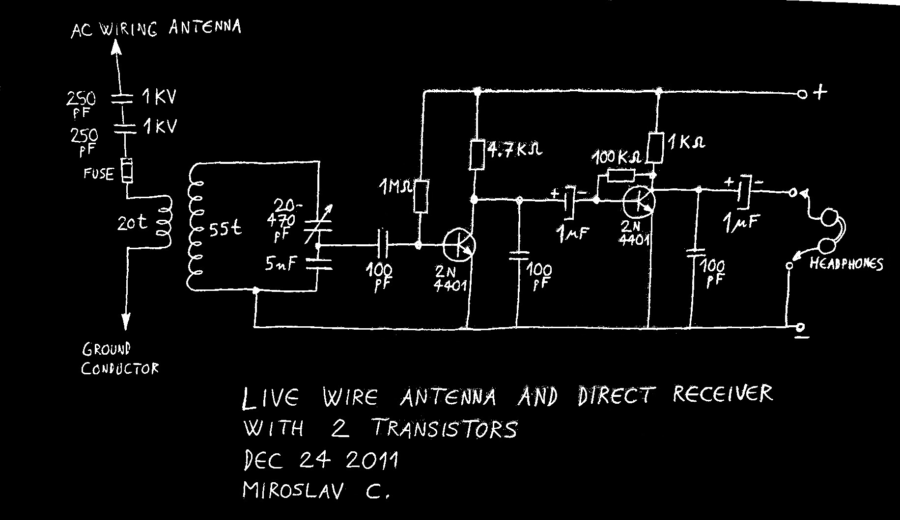
Live Wire Antenna
Using live or neutral wire in AC household wiring as a receiving antenna is feasible only with a high-voltage capacitor inserted between the receiver antenna terminal and the live or neutral wire. This AC wiring antenna solution is often considered...

Antenna ground loop Isolator
A ground loop in your AV system caused by antenna connection or TV cable is very common if you have your computer connected to the same system. This type of ground loop problem can be solved by using suitable isolation...

Car Windscreen Loop Antenna
If you do not like the whip antenna on your car, you may try this alternative circuit. A one-turn loop is installed in the windscreen of the car, keeping possibly away from the metal structure of the car. This loop...