


INA326 327 a single power PID Proportional - Integral - Derivative temperature control loop circuit
#INA326
#INA327
#PID control
#temperature control
#proportional-integral-derivative
#single power
#control loop
#sensor circuit
#feedback system
#thermal regulation
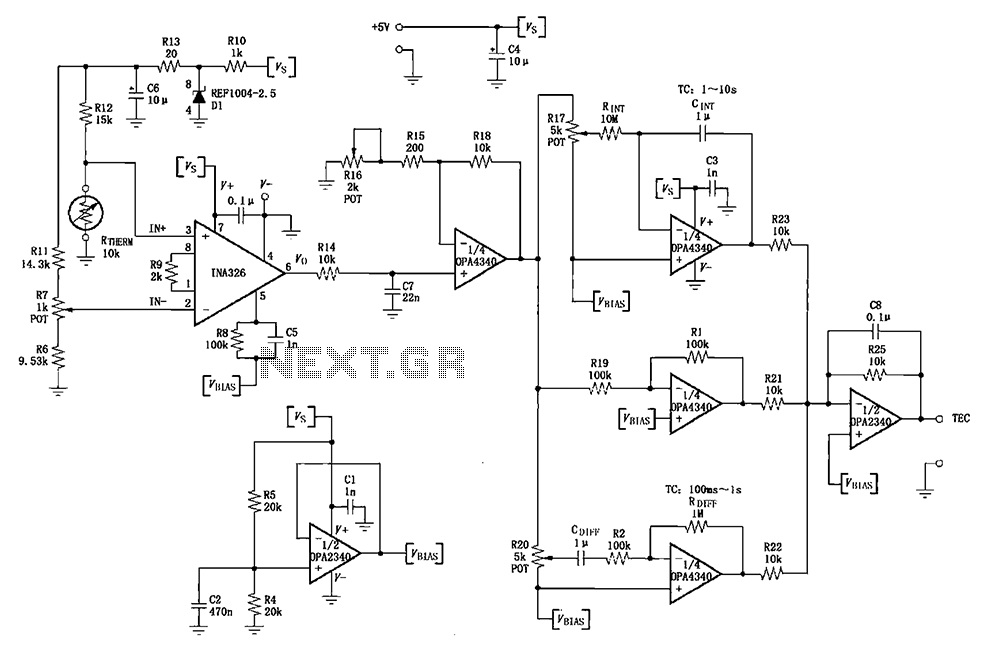
Description: The INA326/327 forms a single power PID (proportional-integral-derivative) controller as illustrated in the temperature control loop. This circuit is primarily designed for temperature measurement and control. A thermistor, designated as RTHERM, detects temperature changes and converts them into an electrical signal, which is then input to the INA326/327. The signal is amplified and output to an operational amplifier (OPA4340) for further amplification and adjustment. This output is subsequently processed through three operational amplifiers (OPA4340) configured as a scaling circuit, integrating circuit, and differentiating circuit, collectively forming the PID controller. The final output is synthesized by a second operational amplifier (OPA2340). Potentiometer R7 is utilized to set the desired temperature, allowing for adjustment so that the initial output from the RTHERM thermistor corresponds to zero, thereby establishing the initial temperature reference point. Potentiometer R16 is employed to adjust the loop gain, optimizing the values for the proportional, integral, and differential components of the circuit. Additionally, potentiometers R17 and R20 are used to fine-tune the integrating circuit and the differential input levels, ensuring they reach their optimal values. A second operational amplifier (OPA2340) is configured as a voltage follower to serve as a bias current generator, providing low-impedance output bias current to each circuit.
The described circuit is an advanced temperature control system that integrates multiple operational amplifiers to achieve precise temperature regulation through PID control. The thermistor RTHERM plays a critical role in sensing temperature variations and translating these changes into a corresponding electrical signal. This signal is first processed by the INA326/327, which is designed to amplify low-level signals with high accuracy and precision.
The operational amplifier OPA4340 is employed in a dual capacity: first for signal amplification and then for further processing in the PID control loop. The use of three OPA4340 amplifiers allows for a modular approach to scaling, integrating, and differentiating the signal, which is essential for implementing the PID algorithm effectively. The integration of these stages ensures that the control system can react to both instantaneous changes (via the proportional component) and accumulated errors over time (via the integral component), while also considering the rate of change of the error (via the derivative component).
The potentiometers are strategically placed within the circuit to facilitate fine-tuning of the various parameters that govern the PID control process. By adjusting R7, the user can establish a baseline temperature, while R16 allows for the optimization of loop gain, ensuring that the system responds appropriately to deviations from the set point. The adjustments via R17 and R20 further refine the performance of the integrating and differential circuits, contributing to the overall stability and responsiveness of the temperature control loop.
The final output stage, utilizing the OPA2340 as a voltage follower, is critical for maintaining low output impedance, which is necessary for driving subsequent stages or loads without significant signal degradation. This configuration ensures that the PID controller can effectively manage the temperature control system with high reliability and accuracy. As shown by INA326/327 constitute a single power PID (proportional - integral - derivative) as shown in the temperature control loop. The circuit is mainly to complete work on the measurement and control of temperature. RTHERM thermistor temperature detection, the temperature change into an electrical signal input INA326/327, amplified output to the operational amplifier 1/4 (OPA4340) further amplification and adjustment, and then into three operational amplifier 1/4 (OPA4340) scaling circuit integrating circuit, a differentiating circuit (ie PID) consisting of treatment, after the final synthesized by 1/2 (OPA2340) output. Potentiometer R7 for setting the temperature, adjust R7 can RTHERM thermistor temperature at the time of initial output is zero, that is, to determine the initial temperature point.
Potentiometer R16 is used to adjust the loop gain adjustment R16 can make the circuit level to the proportional, integral and differential circuit circuit in the most appropriate value. Potentiometer R17, R20, respectively, adjusted for integrating circuit and applied to the differential input of the circuit level, so that in the most appropriate value.
By a 1/2 (OPA2340) constitute a voltage follower as a bias current generator to provide low-impedance output bias current to each circuit.
The described circuit is an advanced temperature control system that integrates multiple operational amplifiers to achieve precise temperature regulation through PID control. The thermistor RTHERM plays a critical role in sensing temperature variations and translating these changes into a corresponding electrical signal. This signal is first processed by the INA326/327, which is designed to amplify low-level signals with high accuracy and precision.
The operational amplifier OPA4340 is employed in a dual capacity: first for signal amplification and then for further processing in the PID control loop. The use of three OPA4340 amplifiers allows for a modular approach to scaling, integrating, and differentiating the signal, which is essential for implementing the PID algorithm effectively. The integration of these stages ensures that the control system can react to both instantaneous changes (via the proportional component) and accumulated errors over time (via the integral component), while also considering the rate of change of the error (via the derivative component).
The potentiometers are strategically placed within the circuit to facilitate fine-tuning of the various parameters that govern the PID control process. By adjusting R7, the user can establish a baseline temperature, while R16 allows for the optimization of loop gain, ensuring that the system responds appropriately to deviations from the set point. The adjustments via R17 and R20 further refine the performance of the integrating and differential circuits, contributing to the overall stability and responsiveness of the temperature control loop.
The final output stage, utilizing the OPA2340 as a voltage follower, is critical for maintaining low output impedance, which is necessary for driving subsequent stages or loads without significant signal degradation. This configuration ensures that the PID controller can effectively manage the temperature control system with high reliability and accuracy. As shown by INA326/327 constitute a single power PID (proportional - integral - derivative) as shown in the temperature control loop. The circuit is mainly to complete work on the measurement and control of temperature. RTHERM thermistor temperature detection, the temperature change into an electrical signal input INA326/327, amplified output to the operational amplifier 1/4 (OPA4340) further amplification and adjustment, and then into three operational amplifier 1/4 (OPA4340) scaling circuit integrating circuit, a differentiating circuit (ie PID) consisting of treatment, after the final synthesized by 1/2 (OPA2340) output. Potentiometer R7 for setting the temperature, adjust R7 can RTHERM thermistor temperature at the time of initial output is zero, that is, to determine the initial temperature point.
Potentiometer R16 is used to adjust the loop gain adjustment R16 can make the circuit level to the proportional, integral and differential circuit circuit in the most appropriate value. Potentiometer R17, R20, respectively, adjusted for integrating circuit and applied to the differential input of the circuit level, so that in the most appropriate value.
By a 1/2 (OPA2340) constitute a voltage follower as a bias current generator to provide low-impedance output bias current to each circuit.

TWH9205 by the integrated circuit consisting of a temperature control circuit automatically
This circuit is used for temperature control in various heating equipment such as water heaters, microwave ovens, air conditioners, refrigerators, fans, and automatic fire extinguishing devices. It includes a negative temperature coefficient (NTC) thermistor as the temperature sensing element and...

AD594 to 597 basic application circuit b
An automatic electric furnace temperature controller is illustrated. The closed circuit consists of a temperature detection output control loop; as the temperature increases, the output voltage rises until it reaches a preset temperature value, at which point the output stops...

Temperature-controlling circuit
The circuit switches the current to an electrical heater on and off to maintain the temperature of a room at 25 ±0.5°C. The temperature sensor is a thermistor that provides a differential input (for reduced noise) to an operational amplifier....

Temperature-Controlled Soldering Iron
One reason commercial soldering stations are expensive is that they generally require soldering irons with built-in temperature sensors, such as thermocouples. This circuit eliminates the need for a special sensor by sensing the temperature of a soldering iron heating element...

Temperature Fan Controller
This circuit controls very accurately a fan of any size. Just adjust the associated resistors for a different type like the R6 resistor of 100 ohm, 2 watt type and you're all set. The above circuit diagram is for a...

Host computer automatic temperature control circuit
When running large-scale software or games, a computer's internal temperature can increase significantly, especially during hot summer months. Although the machine is equipped with a CPU and graphics card fan, poor hot air circulation prevents immediate removal of heat from...

On-Off Temperature Control
This circuit controls a load, specifically a DC brushless fan, based on temperature compared to a setpoint. The transducer used is a diode operating in the forward polarization regime. When forward-biased, the forward voltage drop across the diode exhibits a...
12 Volt DC Fan Temperature Control
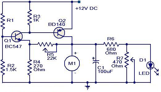
This circuit utilizes two transistors to control the speed of a 12 V DC fan based on temperature variations. A thermistor (R1) is used to sense the temperature. As the temperature rises, the base current of Q1 (BC 547) increases,...
Temperature Control Circuit by Fan
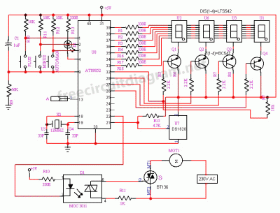
The circuit is designed for temperature control using a fan. It can regulate temperature and also provides temperature indication. All the functions mentioned are monitored.
The temperature control circuit utilizes a fan to maintain a desired ambient temperature within a specified...