


Infra-red Level Detector with 555
#infra-red
#level detection
#proximity sensor
#555 timer
#reflective sensor
#liquid level
#relay
#distance measurement
#non-contact
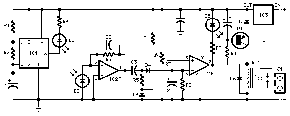
Description: Useful for liquids level detection and proximity devices. Up to 50 cm range, optional relay operation. This circuit is useful in liquids level or proximity detection. It operates detecting the distance from the target by reflection of an infra-red beam. It can safely detect the level of a liquid in a tank without any contact with the liquid itself. The device's range can be set from a couple of cm to about 50 cm by means of a trimmer. Range can vary, depending on infra-red transmitting and receiving LEDs used and is mostly affected by the color of the reflecting surface. Black surfaces lower greatly the device's sensitivity. More: IC1 forms an oscillator driving the infra-red LED by means of 0.8 mSec pulses at 120Hz frequency and about 300mA peak current. D1 & D2 are placed facing the target on the same line, a couple of centimeters apart, on a short breadboard strip. D2 picks-
The circuit operates on the principle of pulse modulation using an infrared LED (D1) to emit an infrared beam toward the target. The reflected beam is detected by a photodiode (D2), which is positioned close to the LED to ensure accurate detection of the reflected signal. The modulation frequency of 120 Hz and pulse width of 0.8 milliseconds are critical for distinguishing the reflected signal from ambient light interference.
The oscillator circuit, represented by IC1, generates the necessary pulse train to drive the LED. The peak current of approximately 300 mA allows for a strong infrared beam, enhancing the detection range. The sensitivity of the circuit can be adjusted using a trimmer potentiometer, which modifies the threshold level for the detection of the reflected signal.
The circuit is capable of detecting distances ranging from a few centimeters up to 50 cm, making it versatile for various applications, including liquid level detection in tanks. The performance of the device can be influenced by the color and texture of the reflecting surface; for example, dark surfaces tend to absorb infrared light, reducing the effective range and sensitivity of the device.
For applications requiring relay operation, the circuit can be designed to include a relay module that activates when the liquid level reaches a predetermined height, allowing for automated control of pumps or alarms. This feature enhances the utility of the circuit in practical scenarios, such as automated water level control in reservoirs or aquariums.
Overall, this infrared-based proximity and level detection circuit offers a non-contact solution for various applications, combining simplicity with effective performance.Useful for liquids level detection and proximity devices Up to 50 cm. range, optional relay operation. This circuit is useful in liquids level or proximity detection. It operates detecting the distance from the target by reflection of an infra-red beam. It can safely detect the level of a liquid in a tank without any contact with the liquid itself. The device`s range can be set from a couple of cm. to about 50 cm. by means of a trimmer. Range can vary, depending on infra-red transmitting and receiving LEDs used and is mostly affected by the color of the reflecting surface. Black surfaces lower greatly the device`s sensitivity. IC1 forms an oscillator driving the infra-red LED by means of 0.8mSec. pulses at 120Hz frequency and about 300mA peak current. D1 & D2 are placed facing the target on the same line, a couple of centimeters apart, on a short breadboard strip. D2 picks-
The circuit operates on the principle of pulse modulation using an infrared LED (D1) to emit an infrared beam toward the target. The reflected beam is detected by a photodiode (D2), which is positioned close to the LED to ensure accurate detection of the reflected signal. The modulation frequency of 120 Hz and pulse width of 0.8 milliseconds are critical for distinguishing the reflected signal from ambient light interference.
The oscillator circuit, represented by IC1, generates the necessary pulse train to drive the LED. The peak current of approximately 300 mA allows for a strong infrared beam, enhancing the detection range. The sensitivity of the circuit can be adjusted using a trimmer potentiometer, which modifies the threshold level for the detection of the reflected signal.
The circuit is capable of detecting distances ranging from a few centimeters up to 50 cm, making it versatile for various applications, including liquid level detection in tanks. The performance of the device can be influenced by the color and texture of the reflecting surface; for example, dark surfaces tend to absorb infrared light, reducing the effective range and sensitivity of the device.
For applications requiring relay operation, the circuit can be designed to include a relay module that activates when the liquid level reaches a predetermined height, allowing for automated control of pumps or alarms. This feature enhances the utility of the circuit in practical scenarios, such as automated water level control in reservoirs or aquariums.
Overall, this infrared-based proximity and level detection circuit offers a non-contact solution for various applications, combining simplicity with effective performance.Useful for liquids level detection and proximity devices Up to 50 cm. range, optional relay operation. This circuit is useful in liquids level or proximity detection. It operates detecting the distance from the target by reflection of an infra-red beam. It can safely detect the level of a liquid in a tank without any contact with the liquid itself. The device`s range can be set from a couple of cm. to about 50 cm. by means of a trimmer. Range can vary, depending on infra-red transmitting and receiving LEDs used and is mostly affected by the color of the reflecting surface. Black surfaces lower greatly the device`s sensitivity. IC1 forms an oscillator driving the infra-red LED by means of 0.8mSec. pulses at 120Hz frequency and about 300mA peak current. D1 & D2 are placed facing the target on the same line, a couple of centimeters apart, on a short breadboard strip. D2 picks-

4 time ON-OFF relay circuit
A circuit is required where, upon power application, a timer triggers, keeping a relay in the off state. Once the timer completes its cycle, the relay will activate.
The circuit design consists of a timer integrated with a relay to control...

pwm using 555 timer ic
The 555 integrated circuit (IC) is configured in monostable mode of operation. In this mode, the output remains LOW (0V) when there is no trigger input. When a trigger is applied through pin 2, the output switches to HIGH (Vcc)...

Video Line Bar Generator Circuit
A 555 timer and a dual 556 timer are used to generate a basic video signal, as illustrated in the schematic. The first timer operates in astable mode, producing synchronization pulses with a period ranging from 4.7 to 8 units....

Electronic Dice circuit
The IC1 is a 555 timer IC configured for astable operation, generating clock pulses that are fed to IC2 through a 10K resistor. IC2 is a 10-stage counter, with output 6 (pin 5) connected to RESET (pin 15), resulting in...
Laser Controlled ON - OFF Switch
This circuit is designed around a 555 timer and utilizes a minimal number of components. Due to its simplicity, it can be easily constructed and operated by beginners.
The circuit leverages the 555 timer IC, which is a versatile and widely...

low current relay circuit
This circuit design for a low current relay is intended for use in battery-operated electronic devices, with an operating current in microamperes (µA). It utilizes a bistable relay and additional components to enable the relay to function similarly to a...

555 Timer Clap Switch
This 555 timer clap switch circuit electronic project is designed using common electronic components.
The 555 timer clap switch circuit utilizes a 555 timer IC in a monostable configuration to create a sound-activated switch. The circuit is triggered by a...

555 light tester circuit diagram
The circuit utilizes photoelectric sensors and a 555 timer to respond to music prompts. The illumination sensor components consist of photovoltaic cells (2CR33). When the light level drops below the optimal learning illumination of 100 lux, the 2CR33 exhibits high...

Latest British Police Car Siren circuit
The 555 timer on the right is configured as an alarm sound generator, while the second 555 timer on the left operates as a 1 Hz astable multivibrator. The output from the left timer modulates the frequency of the right...