


Infra-Red Sensor/Monitor
#infra-red
#IR sensor
#low power
#comparator
#reference device
#notebook
#PDA
#ultra-low current
#monitor
#detection
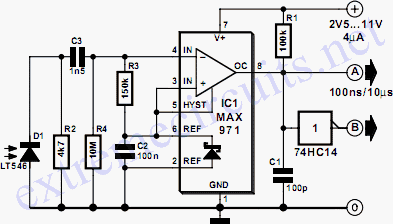
Description: The sensor/monitor depicted in the diagram activates the host system upon detecting infrared (IR) signals. It consumes very little supply current, allowing it to remain continuously operational in devices such as notebook computers or PDAs. The ultra-low current drain, with a maximum of 4 µA and a typical value of 2.5 µA, is mainly attributed to the comparator/reference device, IC1. The circuit is designed for non-carrier systems common in infrared Data Association (IrDA) applications. However, it is also compatible with carrier protocols used by TV remote controllers and the Newton/Sharp ASK (amplitude shift keying protocol developed by Sharp for the Apple Newton). The effective range for 115,200-baud IrDA is approximately 6 inches (15 cm), while the range for 2400-baud IrDA extends beyond 12 inches (30 cm). The system exhibits good immunity to ambient light, although bright flashes may cause false triggers. To mitigate such triggers, the system checks for IR activity after waking and returns to sleep mode if no activity is detected. The sensor, D1, is a relatively large-area photodiode housed in an IR-filter material, generating around 60 µA under heavy illumination and 400 mV when open-circuited. Most photodiodes can be utilized in this application. The operation occurs in photovoltaic mode without an applied bias. This mode is slower and not commonly used in photodiode circuits, but speed is not critical in this context. The use of photovoltaic mode simplifies the circuit and significantly reduces power consumption. In contrast, a conventional configuration, such as photoconductive mode, would result in increased quiescent current by approximately ten times due to photo currents sourced by the bias network from ambient light.
The described sensor/monitor circuit is particularly useful in low-power applications where energy efficiency is critical. The choice of a large-area photodiode allows for enhanced sensitivity to IR signals, making it suitable for various infrared communication protocols. The circuit's design, which prioritizes low current consumption, ensures that it can remain active without significantly draining the battery of portable devices.
The comparator IC (IC1) plays a crucial role in processing the signals received from the photodiode. It compares the voltage generated by the photodiode against a predefined threshold, determining whether the IR signal is present or not. This process is integral to the operation of the device, as it dictates when the host system should be activated. The design also includes provisions for filtering out ambient light interference, ensuring that the sensor responds primarily to IR signals of interest.
In practical applications, the circuit can be integrated into various consumer electronics, including remote controls, smart home devices, and portable computing devices, where maintaining a low power profile is essential. The ability to operate effectively in both non-carrier and carrier protocols broadens its usability across different systems. Furthermore, the inherent design simplicity and low power consumption make it an attractive solution for engineers seeking to implement IR detection in their products.The sensor/monitor shown in the diagram wakes up` the host system on detection of infra-red (IR) signals. It draws so little supply current that it can remain on continuously in a notebook computer or PDA device.
Its ultra-low current drain (4 µA maximum, 2. 5 µA typical) is primarily that of the comparator/reference device, IC1. The circuit is int ended for the non-carrier systems common in infra-red Data Association (IrDA) applications. It also operates with carrier protocols such as those of TV remote controllers and Newton/Sharp ASK (an amplitude shift keying protocol developed by Sharp and used in the Apple Newton). The range for 115, 000-baud IrDA is limited to about 6 in (15 cm), but for 2400-baud IrDA, it improves to more than 12 in (30 cm).
Immunity to ambient light is very good, although bright flashes usually cause false triggers. To handle such triggers, the system simply looks for IR activity after waking and then returns to sleep mode if none is present. The sensor shown, D1, a relatively large-area photo-diode packaged in an IR-filter material, produces about 60 µA when exposed to heavy illumination, and 400mV when open-circuited.
Most photo-diodes may be used. Operation is in the photovoltaic mode without applied bias. This mode is slow and not generally used in photo-diode circuits, but speed is not essential here. The photovoltaic mode simplifies the circuit and saves a significant amount of power. In a more conventional configuration, for instance, photo-conductive, photo currents caused by ambient light and sourced by the bias network would increase the quiescent current about ten times.
The described sensor/monitor circuit is particularly useful in low-power applications where energy efficiency is critical. The choice of a large-area photodiode allows for enhanced sensitivity to IR signals, making it suitable for various infrared communication protocols. The circuit's design, which prioritizes low current consumption, ensures that it can remain active without significantly draining the battery of portable devices.
The comparator IC (IC1) plays a crucial role in processing the signals received from the photodiode. It compares the voltage generated by the photodiode against a predefined threshold, determining whether the IR signal is present or not. This process is integral to the operation of the device, as it dictates when the host system should be activated. The design also includes provisions for filtering out ambient light interference, ensuring that the sensor responds primarily to IR signals of interest.
In practical applications, the circuit can be integrated into various consumer electronics, including remote controls, smart home devices, and portable computing devices, where maintaining a low power profile is essential. The ability to operate effectively in both non-carrier and carrier protocols broadens its usability across different systems. Furthermore, the inherent design simplicity and low power consumption make it an attractive solution for engineers seeking to implement IR detection in their products.The sensor/monitor shown in the diagram wakes up` the host system on detection of infra-red (IR) signals. It draws so little supply current that it can remain on continuously in a notebook computer or PDA device.
Its ultra-low current drain (4 µA maximum, 2. 5 µA typical) is primarily that of the comparator/reference device, IC1. The circuit is int ended for the non-carrier systems common in infra-red Data Association (IrDA) applications. It also operates with carrier protocols such as those of TV remote controllers and Newton/Sharp ASK (an amplitude shift keying protocol developed by Sharp and used in the Apple Newton). The range for 115, 000-baud IrDA is limited to about 6 in (15 cm), but for 2400-baud IrDA, it improves to more than 12 in (30 cm).
Immunity to ambient light is very good, although bright flashes usually cause false triggers. To handle such triggers, the system simply looks for IR activity after waking and then returns to sleep mode if none is present. The sensor shown, D1, a relatively large-area photo-diode packaged in an IR-filter material, produces about 60 µA when exposed to heavy illumination, and 400mV when open-circuited.
Most photo-diodes may be used. Operation is in the photovoltaic mode without applied bias. This mode is slow and not generally used in photo-diode circuits, but speed is not essential here. The photovoltaic mode simplifies the circuit and saves a significant amount of power. In a more conventional configuration, for instance, photo-conductive, photo currents caused by ambient light and sourced by the bias network would increase the quiescent current about ten times.

Frequency-detecting-comparator
A quad comparator serves as the foundation for a frequency detector that is both faster and more cost-effective than more complex alternatives utilizing frequency-to-voltage converter chips. Positive feedback through a 5 MΩ resistor enables the circuit to detect changes as...

remote tester
The remote tester circuit operates similarly to a dark sensor using a BC557 transistor. An LDR has been substituted with an IR sensor, specifically the TSOP 1738. The circuit functions as a remote tester; when a remote control switch is...
Null-detector
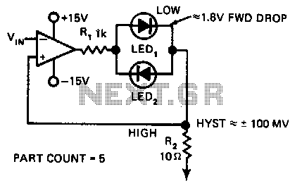
In this indicating comparator circuit, R2 sets the hysteresis. If the 741 saturates at ±12 V, the current in R1 will be approximately ±10 mA if a 0.1 V hysteresis is desired. More: Then 0.1 V/10 mA ~ 100.
The indicating...

Infrared (IR) Proximity (Distance) Sensor
The photodiode is utilized to detect infrared (IR) light reflected from an object. However, it also picks up IR light generated by ambient conditions, which can lead to false detections. To mitigate this issue, it is essential to filter out...
Infra-red Level Detector
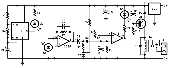
This circuit is useful in liquids level or proximity detection. It operates detecting the distance from the target by reflection of an infra-red beam. It can safely detect the level of a liquid in a tank without any contact with...

Window comparator
This circuit produces an output of 0V when the input voltage is within a specified range defined by two reference voltages. When the input voltage falls outside this range, the output becomes positive. Two operational amplifiers (op-amps) function as voltage...

Dual limit comparator
This circuit provides a positive output when the input voltage exceeds 8 volts. Within these limits, the output remains negative. The threshold for the positive output is set by the ratio of resistors R1 and R2, while the threshold for...
Comparator with time out
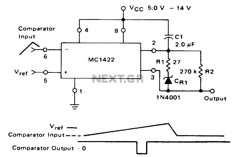
The MC1422 functions as a comparator with the input at Pin 5. The frequency of the output pulses, dependent on the values of R2 and C1 as indicated, is approximately 2 Hz, with a pulse width of 0 ms at...

ir remote control tester
While developing an infrared (IR) extender circuit, a method was required to measure the relative intensities of different infrared light sources. This circuit is the culmination of that research. It utilizes a photodiode, specifically the SFH2030, as the infrared sensor....