


Intelligent Ultrasonic Ranging IC 4Y4 form a monolithic liquid crystal display rangefinder circuit diagram
#ultrasonic
#ranging
#LCD display
#transmitter
#receiver
#measurement
#distance sensor
#4Y4
#rangefinder

Description: The 4Y4 is a monolithic liquid crystal display rangefinder circuit. The instrument comprises an ultrasonic transmitter, a receiver, an LCD display, buttons, switches, and a buzzer (or speaker). To simplify wiring, the 4Y4 is directly welded to the back of the LCD display panel. The range measurements include distances of 2 to 4 feet, 8 feet, 23 feet to 26 feet, and 28 to 30 feet. R1 functions as the current limiting resistor for the transmitting circuit. Resistors R2 to R4 are used for amplifying the receiving external components. C3 serves as an automatic reset capacitor. A 455 kHz oscillator circuit utilizes inexpensive piezoelectric ceramic filters instead of quartz (JT), with capacitors C1 and C2 providing oscillation. SB represents the push-button switch. C4 is used for power supply decoupling. The 4Y4 can drive a piezoelectric ceramic buzzer or a micro speaker; however, to drive a larger speaker, a Darlington pair (VT1, VT2) is required as a power amplifier. R6 is the current limiting resistor for VT1. Additionally, the 4Y4 can interface with external transmission or reception circuits. For instance, the sensitivity of the waterproof ultrasonic probe is only 1/10th of that of a standard probe, allowing for measurements without an external transceiver at a distance of 50 cm. An expanded circuit can enhance reception sensitivity to meet specific underwater ranging requirements.
The 4Y4 rangefinder circuit integrates multiple components to achieve effective distance measurement using ultrasonic technology. The ultrasonic transmitter emits sound waves, which reflect off objects and are received by the ultrasonic receiver. The circuit processes these signals and displays the calculated distance on the LCD screen. The inclusion of buttons and switches allows for user interaction to select measurement modes or reset the device.
The design features a robust power management system, with C4 ensuring stable power supply to prevent fluctuations that could affect measurement accuracy. The use of piezoelectric ceramic filters in the oscillator circuit (455 kHz) is a cost-effective solution that maintains performance while reducing component complexity. The oscillation capacitors (C1 and C2) are crucial for maintaining the frequency stability of the oscillator, which is essential for accurate distance measurements.
The Darlington pair configuration (VT1, VT2) amplifies the signal sufficiently to drive larger speakers, enabling audible feedback for the user. The current limiting resistor (R6) protects the circuit from excessive current that could damage the transistors. The design also allows for adaptability with external circuits, enhancing the functionality of the rangefinder. This feature is particularly beneficial in specialized applications, such as underwater measurements, where increased sensitivity is necessary.
Overall, the 4Y4 circuit exemplifies an efficient and versatile approach to ultrasonic distance measurement, integrating various electronic components to deliver a reliable and user-friendly instrument.4Y4 constituted by a monolithic liquid crystal display rangefinder circuit as shown in FIG. The instrument includes an ultrasonic transmitter, a receiver, LCD display, buttons, switches and a buzzer (or speaker), in order to simplify wiring, 4Y4 welded directly in the back of the display panel LCD. 4Y4 first 2 to 4 feet, 8 feet, 23 feet to 26 feet and 28 to 30 do not. R1 is transmitting circuit current limiting resistor. R2 ~ R4 to amplifier receiving external components. C3 to boot automatically reset capacitor. 455kHz oscillator circuit using an inexpensive piezoelectric ceramic filters instead of quartz (JT), C1 and C2 for the oscillation capacitor.
SB for the push button switch. C4 power supply decoupling capacitors. 4Y4 only drive the piezoelectric ceramic buzzer or micro Xiangqi, in order to drive the speaker, but also need to increase the level ~ Darlington (VT1, VT2) to use as a power amplifier. Current limiting resistor R6 of VT1. According to actual needs, 4Y4 also received external transmission circuit or reception circuit. For example, the sensitivity of the ultrasonic probe waterproof seal is only 1/10 of ordinary probe can only measure without external transceiver at 50cm distance, the increased expansion circuit can improve the reception sensitivity to meet the special requirements of underwater ranging.
The 4Y4 rangefinder circuit integrates multiple components to achieve effective distance measurement using ultrasonic technology. The ultrasonic transmitter emits sound waves, which reflect off objects and are received by the ultrasonic receiver. The circuit processes these signals and displays the calculated distance on the LCD screen. The inclusion of buttons and switches allows for user interaction to select measurement modes or reset the device.
The design features a robust power management system, with C4 ensuring stable power supply to prevent fluctuations that could affect measurement accuracy. The use of piezoelectric ceramic filters in the oscillator circuit (455 kHz) is a cost-effective solution that maintains performance while reducing component complexity. The oscillation capacitors (C1 and C2) are crucial for maintaining the frequency stability of the oscillator, which is essential for accurate distance measurements.
The Darlington pair configuration (VT1, VT2) amplifies the signal sufficiently to drive larger speakers, enabling audible feedback for the user. The current limiting resistor (R6) protects the circuit from excessive current that could damage the transistors. The design also allows for adaptability with external circuits, enhancing the functionality of the rangefinder. This feature is particularly beneficial in specialized applications, such as underwater measurements, where increased sensitivity is necessary.
Overall, the 4Y4 circuit exemplifies an efficient and versatile approach to ultrasonic distance measurement, integrating various electronic components to deliver a reliable and user-friendly instrument.4Y4 constituted by a monolithic liquid crystal display rangefinder circuit as shown in FIG. The instrument includes an ultrasonic transmitter, a receiver, LCD display, buttons, switches and a buzzer (or speaker), in order to simplify wiring, 4Y4 welded directly in the back of the display panel LCD. 4Y4 first 2 to 4 feet, 8 feet, 23 feet to 26 feet and 28 to 30 do not. R1 is transmitting circuit current limiting resistor. R2 ~ R4 to amplifier receiving external components. C3 to boot automatically reset capacitor. 455kHz oscillator circuit using an inexpensive piezoelectric ceramic filters instead of quartz (JT), C1 and C2 for the oscillation capacitor.
SB for the push button switch. C4 power supply decoupling capacitors. 4Y4 only drive the piezoelectric ceramic buzzer or micro Xiangqi, in order to drive the speaker, but also need to increase the level ~ Darlington (VT1, VT2) to use as a power amplifier. Current limiting resistor R6 of VT1. According to actual needs, 4Y4 also received external transmission circuit or reception circuit. For example, the sensitivity of the ultrasonic probe waterproof seal is only 1/10 of ordinary probe can only measure without external transceiver at 50cm distance, the increased expansion circuit can improve the reception sensitivity to meet the special requirements of underwater ranging.

ultrasonic switch sensor
This circuit operates using ultrasonic sound, which is sound at frequencies above 20 kHz, making it inaudible to humans. The circuit generates ultrasonic sound frequencies between 40 kHz and 50 kHz. Similar to other remote control systems, this circuit includes...

ultrasonic measurement circuit
This design circuit is for an electrostatic transducer used in ultrasonic measurement applications. It employs the LM1812 ultrasonic transceiver. The transducer (X1) and the LM1812 work together to transmit a burst of oscillations. The return echo is detected by X1,...

Homebrew Utrasonic Imager
This is the electronic schematic of a homebuilt SONAR system. It utilizes a single piezoelectric transducer for both transmission and reception, which is switched from transmit (TX) to receive (RX) mode using four 4016 analog switches. A high-gain amplifier stage...

Ultrasonic Wave Receiver Circuit Schematic Diagram
Ultrasonic receivers detect an ultrasonic signal emitted by an ultrasonic transmitter at a specific frequency. The received signal is filtered using a band-pass filter circuit that allows only the predetermined frequency range to pass. The output signal is then amplified...

ATV JR TRANSMITTER 440 MHz
This low-power video transmitter is suitable for remote control applications, surveillance, or amateur radio. It employs seven transistors within a crystal oscillator multiplier RF power amplifier chain, along with a high-level video modulator. A supply voltage ranging from 9 to...

Noisy Regen Receiver
The following circuit illustrates a Noisy Regenerative Receiver Circuit Diagram. Features include a Noisy Regenerative Receiver Circuit, which simplifies the process of...
The Noisy Regenerative Receiver Circuit is designed to amplify weak radio frequency signals while also incorporating a regenerative feedback...

Dummy Transmission Circuits for Subcutaneous Transmitter
The project involves the development of a miniature transmitter suitable for implantation in a rat's body, capable of transmitting 416-bit data samples at a rate of 400 samples per second. It is designed to have a detection range of three...

radio mf tx
There has been a longstanding interest in constructing a simple VXO transmitter, though concerns regarding the limited tuning range typically associated with VXOs on busy HF bands have been present. The capability to switch between multiple crystals and cover various...
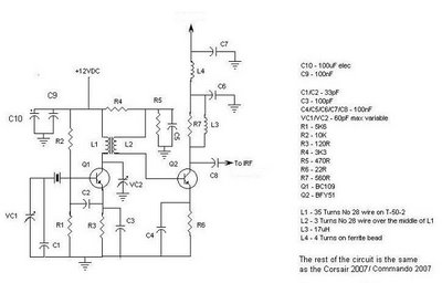
Corsair and Commando TXs
This document provides information about the Corsair and Commando Transmitters designed by Dave Martin of WNKR. It outlines the construction of each transmitter and includes examples created by others. The circuit diagram presented illustrates the initial two stages of a...