


Inverse Heat Conduction
#heat flux
#temperature measurement
#thermal sensor
#inverse heat conduction
#boundary measurement
#noise reduction
#thermal analysis
#sensor calibration
#heat transfer
#temperature stability

Description: Inverse heat conduction methods can be utilized to determine heat flux and temperatures on an inaccessible surface of a wall by measuring the temperature on an accessible boundary. However, the noise present in temperature measurements can lead to instabilities in predicted heat fluxes. It has been demonstrated that predictions can be significantly enhanced by measuring temperature at two locations. Modifying the wall to include an interior thermocouple is often impractical, and its installation may introduce material inhomogeneities that alter heat flow through the wall. Through numerical experiments and sensitivity analysis, it has been shown that incorporating a measurement of the heat flux at the accessible boundary can improve calculations. The objective of this work was to develop a method that allows for stable predictions of heat transfer on an inaccessible boundary without altering the thermal boundary condition that would have existed in the absence of a sensor. A sensor that measures both heat transfer and temperature on an accessible boundary with minimal impact on the boundary condition is described, and experimental results with this sensor are presented. A schematic diagram of the sensor illustrates that a small resistance heater is attached to the accessible boundary of a wall, with its temperature controlled by an electronic feedback loop to track the temperature of a passive temperature sensor mounted nearby. The passive temperature sensor is designed to be very thin, thus minimally affecting the wall boundary condition. The active heater is cooled by an efficient cooling mechanism from behind, such as circulating chilled water or an impinging air or water jet. By measuring the heat added to the active heater, the heat flux through the wall can be determined. The passive temperature sensor is cooled through convection, and the response of the sensor can be expressed mathematically. If the heat transfer coefficients and the environment and coolant temperatures are constant, the heat supplied to the heater becomes linearly proportional to the heat transfer through the substrate. By measuring the heat supplied to the heater, the heat transfer through the wall can be determined. If the heat transfer coefficients remain constant, variations in environmental temperatures simply result in an offset. The heat flux sensor can be operated with different environmental temperatures by applying a correction to the output using the established equation. The concept has been validated with a specific experimental setup using a copper plate heated by a foil heater connected to a variable voltage source. A pair of specially designed resistance temperature detectors (RTDs) were utilized for the active and passive sensors. These RTDs consist of a thin etched platinum foil sandwiched between two layers of Kapton films. The active sensor was cooled from behind using an impinging water jet at a constant flow rate, while a fan was used to maintain a constant cooling effect on the plate. The air and water inlet temperatures were monitored, along with the voltage across the heater, to ensure they remained stable. The response indicated a linear variation as expected, demonstrating the sensor's sensitivity.
The described inverse heat conduction method leverages a dual-sensor system to enhance the accuracy of heat flux and temperature predictions on inaccessible surfaces. The active heater and passive temperature sensor are strategically placed to minimize disturbance to the thermal boundary condition. The electronic feedback loop ensures that the active heater maintains a consistent temperature that closely tracks the passive sensor's readings, allowing for precise calculations of heat transfer rates.
The cooling mechanisms employed are critical for maintaining the operational integrity of the sensors. The use of an impinging jet for the active heater ensures efficient heat dissipation, which is essential for achieving a high heat transfer coefficient. The passive sensor's thin profile is designed to ensure that it does not significantly alter the heat transfer characteristics of the wall, allowing for accurate representation of the thermal conditions present.
The experimental setup, utilizing a copper plate as the test medium, demonstrates the practical application of this method. The specially designed RTDs exhibit excellent performance characteristics, providing reliable temperature measurements necessary for accurate heat flux calculations. The linear response observed during experiments confirms the effectiveness of the sensor design and the methodology employed, paving the way for further research and applications in environments where direct measurement of heat transfer is challenging. This innovative approach offers significant advantages in various fields, including materials science, thermal engineering, and building physics, where understanding heat transfer dynamics is essential.Inverse heat conduction methods can be used to determine heat flux and temperatures on an inaccessible surface of a wall by measuring the temperature on an accessible boundary (TS method, Figure 1). The noise present in any measure of temperature, however, can cause instabilities in the predicted heat fluxes.
It has been shown that the predictioncan be greatly improved by measuring temperature at two locations. Altering the wall to include an interior thermocouple cannot be performed in many applications, and installation of an interior thermocouple can result in material inhomogeneities that change the heat flow through the wall. By numerical experiments and a sensitivity analysis it can be shown that incorporating a measurement of the heat flux at the accessible boundary (TS/HFS method, Figure 2) can be used to improve the calculation.
The objective of this work was to develop a method by which stable predictions of the heat transfer on an inaccessible boundary could be obtained without altering the thermal boundary condition that would have existed were a sensor not present. A sensor that measures both heat transfer and temperature on an accessible boundary with minimal impact on the boundary condition is described and results of experiments with this sensor are presented.
A schematic diagram of the sensor is shown on Figure 3. A small resistance heater (Active heater in Figure 3) is attached to the accessible boundary of a wall, and its temperature is controlled by an electronic feedback loop to track the temperature of a passive temperature sensor (Passive sensor in Figure 3) mounted on the same boundary a short distance away. The passive temperature sensor is very thin so the wall boundary condition is only minimally altered.
The active heater is cooled by an efficient and substantial cooling mechanism from behind (for example, circulating chilled water or an impinging air or water jet). By measuring the heat added to the active heater ( in Figure 3), we can determine the heat flux through the wall as shown by the simple analysis of the heat flux sensor performance given below.
The passive temperature sensor is cooled through convection by a heat transfer coefficient hs. It can easily be shown that the response of the sensor is given by 1). If the heat transfer coefficients (hs and hh) and the environment and coolant temperatures (T, s and T, h) are constant and hh>hs, then the heat supplied to the heater is linearly proportional to the heat transfer through the substrate. By measuring, the heat supplied to the heater (qh``), the heat transfer through the wall (qx``) can be determined.
3 ). If hs and hh are constant, then drifts in T, s and T, h simply result in an offset to. The heat flux sensor can be operated with different T, s and T, h by using the above equation to correct the output. The concept has been tested using the setup shown in Figure 5. A 5. 2 cm x 7. 6 cm copper plate 10 mm thick was used for the wall, and heated using a Minco foil heater connected to a variable voltage source.
A pair of RTDs for the active and passive sensor were specially made for this application. The RTDs consist of a 2. 54 micron thick etched platinum foil sandwiched between two 0. 0254 mm thick Kapton films. The passive and active sensor resistances were 988. 9 ohms and 98. 6 ohms at 20 °C. The RTDs had a nominal TCR of 0. 0035/ °C with dimension 10 mm x 5 mm. The active sensor was cooled from the back using an impinging jet of water at a constant flow rate (160 ml/min) and temperature (30 °C) to provide a high hh, and a fan was used to provide a constant hs to cool the plate. The air and water inlet temperatures (T, =25 °C and T, h=30 °C) were measured along with the voltage across the heater (Vout) as was increased to verify that they remained constant.
The response is shown on Figure 6, and indicates a linear variation as expected. The sensitivity is seen to be
The described inverse heat conduction method leverages a dual-sensor system to enhance the accuracy of heat flux and temperature predictions on inaccessible surfaces. The active heater and passive temperature sensor are strategically placed to minimize disturbance to the thermal boundary condition. The electronic feedback loop ensures that the active heater maintains a consistent temperature that closely tracks the passive sensor's readings, allowing for precise calculations of heat transfer rates.
The cooling mechanisms employed are critical for maintaining the operational integrity of the sensors. The use of an impinging jet for the active heater ensures efficient heat dissipation, which is essential for achieving a high heat transfer coefficient. The passive sensor's thin profile is designed to ensure that it does not significantly alter the heat transfer characteristics of the wall, allowing for accurate representation of the thermal conditions present.
The experimental setup, utilizing a copper plate as the test medium, demonstrates the practical application of this method. The specially designed RTDs exhibit excellent performance characteristics, providing reliable temperature measurements necessary for accurate heat flux calculations. The linear response observed during experiments confirms the effectiveness of the sensor design and the methodology employed, paving the way for further research and applications in environments where direct measurement of heat transfer is challenging. This innovative approach offers significant advantages in various fields, including materials science, thermal engineering, and building physics, where understanding heat transfer dynamics is essential.Inverse heat conduction methods can be used to determine heat flux and temperatures on an inaccessible surface of a wall by measuring the temperature on an accessible boundary (TS method, Figure 1). The noise present in any measure of temperature, however, can cause instabilities in the predicted heat fluxes.
It has been shown that the predictioncan be greatly improved by measuring temperature at two locations. Altering the wall to include an interior thermocouple cannot be performed in many applications, and installation of an interior thermocouple can result in material inhomogeneities that change the heat flow through the wall. By numerical experiments and a sensitivity analysis it can be shown that incorporating a measurement of the heat flux at the accessible boundary (TS/HFS method, Figure 2) can be used to improve the calculation.
The objective of this work was to develop a method by which stable predictions of the heat transfer on an inaccessible boundary could be obtained without altering the thermal boundary condition that would have existed were a sensor not present. A sensor that measures both heat transfer and temperature on an accessible boundary with minimal impact on the boundary condition is described and results of experiments with this sensor are presented.
A schematic diagram of the sensor is shown on Figure 3. A small resistance heater (Active heater in Figure 3) is attached to the accessible boundary of a wall, and its temperature is controlled by an electronic feedback loop to track the temperature of a passive temperature sensor (Passive sensor in Figure 3) mounted on the same boundary a short distance away. The passive temperature sensor is very thin so the wall boundary condition is only minimally altered.
The active heater is cooled by an efficient and substantial cooling mechanism from behind (for example, circulating chilled water or an impinging air or water jet). By measuring the heat added to the active heater ( in Figure 3), we can determine the heat flux through the wall as shown by the simple analysis of the heat flux sensor performance given below.
The passive temperature sensor is cooled through convection by a heat transfer coefficient hs. It can easily be shown that the response of the sensor is given by 1). If the heat transfer coefficients (hs and hh) and the environment and coolant temperatures (T, s and T, h) are constant and hh>hs, then the heat supplied to the heater is linearly proportional to the heat transfer through the substrate. By measuring, the heat supplied to the heater (qh``), the heat transfer through the wall (qx``) can be determined.
3 ). If hs and hh are constant, then drifts in T, s and T, h simply result in an offset to. The heat flux sensor can be operated with different T, s and T, h by using the above equation to correct the output. The concept has been tested using the setup shown in Figure 5. A 5. 2 cm x 7. 6 cm copper plate 10 mm thick was used for the wall, and heated using a Minco foil heater connected to a variable voltage source.
A pair of RTDs for the active and passive sensor were specially made for this application. The RTDs consist of a 2. 54 micron thick etched platinum foil sandwiched between two 0. 0254 mm thick Kapton films. The passive and active sensor resistances were 988. 9 ohms and 98. 6 ohms at 20 °C. The RTDs had a nominal TCR of 0. 0035/ °C with dimension 10 mm x 5 mm. The active sensor was cooled from the back using an impinging jet of water at a constant flow rate (160 ml/min) and temperature (30 °C) to provide a high hh, and a fan was used to provide a constant hs to cool the plate. The air and water inlet temperatures (T, =25 °C and T, h=30 °C) were measured along with the voltage across the heater (Vout) as was increased to verify that they remained constant.
The response is shown on Figure 6, and indicates a linear variation as expected. The sensitivity is seen to be

PC Temperature Meter
This is a four-channel temperature measurement adapter that works without an external power supply. It is suitable for measuring temperature and logging its data with a PC. The circuit diagram is very simple and no adjustment is required; everybody will...

Thermally Operated Direction Detector
A heat-sensitive sensor can be utilized to create a direction detector. This type of sensor responds to minimal heat. The specific sensor used in this design features a sensitive surface that has been divided into two sections. Consequently, it can...

Temperature-measuring-add-on-for-dmm-digital-voltmeter
The DVM-to-temperature adapter is constructed around a single integrated circuit (IC), the National LM10. This micropower IC features a stable 0.2 V reference, a reference amplifier, and a general-purpose operational amplifier. The circuit is designed to operate within a linear...
DIY Digital Thermometer
This DIY digital thermometer circuit can measure temperatures up to 150 °C with an accuracy of ±1 °C. The temperature is displayed on a 1V full-scale deflection (FSD) moving-coil voltmeter or digital voltmeter. An operational amplifier IC 741 (IC3) provides...

AMP-04 0 F 400 temperature measurement circuit
AMP-04 is a single-supply, single resistor gain adjustment circuit with an input voltage drift of less than 150 pV, a current drift of 5 nA, and a temperature drift of 8 pA/°C. The gain nonlinearity is 0.005% of the high-resolution...
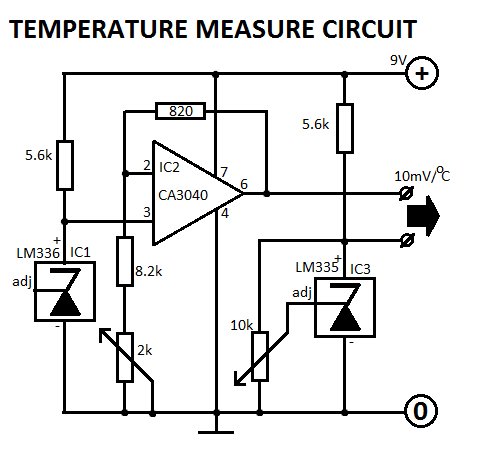
LM336 Temperature Measurement Circuit
This circuit is designed for Fahrenheit measurements, with the freezing point set at 320°F. At 2120°F, P2 is adjusted to achieve an output voltage of 0.9V.
The circuit operates by utilizing a temperature sensor that converts temperature readings into a corresponding...

Dynamic noise reduction with DC volume control
A dynamic noise reduction circuit and a DC volume and tone balance control circuit, which are applied to the input stage and the discharge line between the amplifier.
The described circuit configuration incorporates two primary functions: dynamic noise reduction and volume/tone...

Treasury temperature measurement alarm circuit diagram F007 5G1555 F033
The temperature alarm circuit shown in the figure consists of an inverting amplifier (IC1), a comparison amplifier (IC2), a low-frequency multivibrator (IC3), a controllable oscillation frequency multivibrator (IC4), a bridge measurement network, a speaker (Y), and a power supply circuit....

The Follow-Me Rover robot circuit
The device utilizes body heat to identify and track its human operator. Central to its heat-seeking function is the Devantech TPA81 Thermal Sensor Array, which features an array of eight horizontally mounted detectors. Each detector is capable of sensing infrared...