


Latching Continuity Checker
#continuity checker
#latching circuit
#short detection
#open detection
#sensor
#testing
#electronics
#circuit protection

Description: This circuit detects brief shorts or opens. When S2 is in the up position, the circuit indicates continuity by lighting LED1. U1A and U1B are configured as an R-S flip-flop. SI resets the tester. When S2 is in the down position, a momentary interruption in continuity will light LED1. This tester is effective for detecting intermittent shorts or opens.
The circuit operates primarily as a continuity tester, designed to identify both short circuits and open circuits in electrical components or wiring. The core of the circuit consists of an R-S flip-flop formed by operational amplifiers U1A and U1B. The configuration allows for stable output states that indicate whether continuity exists in the circuit under test.
When switch S2 is toggled to the up position, the circuit enters a state where it checks for continuity. If a complete path exists, LED1 illuminates, signaling that continuity is present. This feature is essential for ensuring that connections are intact and functioning correctly.
The reset functionality is provided by switch SI, which, when activated, clears the flip-flop, ensuring that the tester can be reset before performing a new test. This is crucial for maintaining accurate readings and preventing false indications from previous tests.
In the down position, switch S2 allows the circuit to detect momentary interruptions in continuity. This mode is particularly useful for identifying intermittent faults that may not be present during a static test. When a break in continuity occurs, LED1 lights up, providing immediate visual feedback to the user.
Overall, this circuit is a practical tool for troubleshooting electrical systems, offering a straightforward method for detecting both persistent and transient faults in wiring and components. This circuit detects brief shorts or opens. When S2 is in the up position, the circuit indicates if there is or was continuity by lighting LED1. U1A and U1B are connected as an R-S flip-flop. SI resets the tester. When S2 is in the down position, a momentary interruption in continuity will light LED1. This tester is good for detecting intermittent shorts or opens.
The circuit operates primarily as a continuity tester, designed to identify both short circuits and open circuits in electrical components or wiring. The core of the circuit consists of an R-S flip-flop formed by operational amplifiers U1A and U1B. The configuration allows for stable output states that indicate whether continuity exists in the circuit under test.
When switch S2 is toggled to the up position, the circuit enters a state where it checks for continuity. If a complete path exists, LED1 illuminates, signaling that continuity is present. This feature is essential for ensuring that connections are intact and functioning correctly.
The reset functionality is provided by switch SI, which, when activated, clears the flip-flop, ensuring that the tester can be reset before performing a new test. This is crucial for maintaining accurate readings and preventing false indications from previous tests.
In the down position, switch S2 allows the circuit to detect momentary interruptions in continuity. This mode is particularly useful for identifying intermittent faults that may not be present during a static test. When a break in continuity occurs, LED1 lights up, providing immediate visual feedback to the user.
Overall, this circuit is a practical tool for troubleshooting electrical systems, offering a straightforward method for detecting both persistent and transient faults in wiring and components. This circuit detects brief shorts or opens. When S2 is in the up position, the circuit indicates if there is or was continuity by lighting LED1. U1A and U1B are connected as an R-S flip-flop. SI resets the tester. When S2 is in the down position, a momentary interruption in continuity will light LED1. This tester is good for detecting intermittent shorts or opens.

Sensor-Activated Relay Pulser Circuit
A sensor activates transistor Q1 to turn on the low-frequency 555 oscillator, which generates pulses to control LAMP II. The sensor may respond to variations in light or temperature. Either resistor RA or RB can function as the sensor, depending...

Field disturbance sensor-alarm
The change in ambient light triggers the alarm by changing the resistance of LDR1 and LDR2.
The circuit utilizes two light-dependent resistors (LDR1 and LDR2) to detect variations in ambient light levels. LDRs are passive components that exhibit a change in...

Pots water alarm circuit
The flowers in pots require watering, as relying solely on the observation of moist soil surfaces can be unreliable. To address this issue, a flower watering indicator has been developed. This circuit includes a field effect transistor (VT1), a second...

Quick On-Board Junction TesterCircuit
Short circuits or broken PCB tracks can be easily identified using a multimeter; however, this tool may yield inaccurate results when testing the efficiency of a transistor or diode unless the component is unsoldered and removed from the PCB. Another...

testing ddl s circuit
A guide will be posted on how to test a DDL circuit before integrating the LD. The process aims to ensure clarity and accuracy throughout.
To properly test a DDL (Direct Drive Laser) circuit before adding the LD (Laser Diode), several...

Electronics Projects Circuits
Over 1400 top electronics projects and electronic circuits with photos, datasheets, and easy-to-read schematics, along with explanations of how they work and how to build them.
The collection comprises a vast array of electronics projects suitable for enthusiasts and professionals alike....
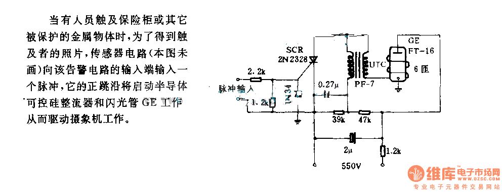
The alarm circuit diagram for safety box and other metal objects
When an individual touches the safety box or other protected metal objects, the sensor circuit generates a pulse to the alarm circuit. The positive edge of this pulse activates the semiconductor and thyristor flash GE, subsequently triggering the camera to...

Simple continuity checker
The pitch of the tone is dependent upon the resistance under test. The tester will respond to resistance of hundreds of kilohms, yet it is possible to distinguish differences of just a few tens of ohms in low-resistance circuits. Q1...

Wire Break Sensor Alarm Circuit Schematic
The circuit of a loop sensor-based simple security alarm is described here. The sensor loop consists of a short length of thin enamelled copper wire.
The loop sensor security alarm operates on the principle of detecting interruptions in the circuit formed...