


lie detector circuit diagram
#lie detector
#skin resistance
#affective state
#sensor
#biofeedback
#emotional response
#conductivity
#measurement

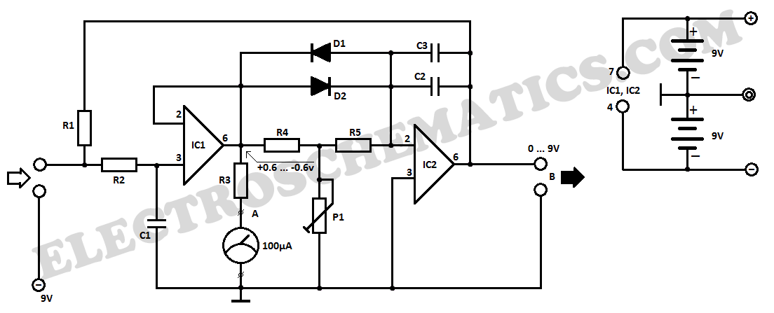
Description: This lie detector circuit diagram provides two readings: one for challenging questions directed at the subject and another to display the subject's emotional state in general. The emotional states are detected not only by heart rate variations and perspiration but also by an increase in skin moisture, which decreases resistance and triggers the operation of the lie detector. Two electrodes can be used as flexible wires, wrapped around the fingers or wrist. To avoid interference from environmental conditions, the device must be powered by two 9-volt batteries. Each change in resistance, and consequently the voltage at the input circuit, will be amplified by operational amplifier A1, which also acts as a separator. The output signal will influence the deflection of the measuring instrument through resistor R3. The general emotional state of an individual can be monitored by measuring the average resistance of the skin over a period of time. An indicator device connected to point B of the circuit provides a visual output. Operational amplifier A2 is configured as an integrator, allowing the circuit to automatically adjust according to the average skin resistance. The duration for measuring skin resistance is determined by resistors R5, capacitor C2, and capacitor C3. Until this time elapses, the lie detector does not provide an indication, although diodes D1 and D3 allow for a rapid response from the circuit. Potentiometer P1 enables adjustment of the circuit's response time. Since skin resistance varies among individuals, it may be necessary to adjust the resistance value of R1. This resistor can be replaced with a potentiometer. A high reading on the output connected to point B indicates that the subject's skin resistance is low (which is characteristic of individuals with sweaty hands) and suggests that the value of R1 should be decreased.
This lie detector circuit is designed to assess physiological responses that may indicate deception. It utilizes two primary physiological metrics: skin resistance and heart rate. The electrodes, positioned on the subject's fingers or wrist, measure variations in skin conductance, which is influenced by sweat production—a common response to stress or anxiety. The circuit's reliance on dual 9-volt batteries ensures stable operation, minimizing the risk of fluctuations that could affect readings.
Operational amplifier A1 serves a dual purpose; it amplifies the changes in voltage corresponding to skin resistance and acts as a signal separator, ensuring that the output is clean and accurate for further processing. The output signal is then directed to a measuring instrument via resistor R3, allowing for real-time monitoring of the subject's emotional state.
Operational amplifier A2 functions as an integrator, smoothing out the fluctuations in skin resistance readings over time. This feature is crucial for distinguishing between normal variations in skin conductance and significant changes that may indicate deceptive behavior. The integration time is adjustable through the combination of R5, C2, and C3, allowing the user to tailor the circuit's responsiveness to the specific characteristics of the subject being tested.
The inclusion of diodes D1 and D3 enhances the circuit's responsiveness, providing immediate feedback during the initial stages of measurement. The potentiometer P1 allows for fine-tuning of the delay before the circuit begins to indicate results, accommodating individual differences in physiological responses.
Adjustability is a key feature of this circuit, particularly with the resistance value of R1. By incorporating a potentiometer in place of R1, the user can calibrate the device for different subjects, ensuring that the lie detector remains sensitive to variations in skin conductance that may arise from individual physiological differences. This adaptability is essential for maintaining the accuracy and reliability of the lie detection process.This lie detector circuit diagram will accord two readings: one for difficult questions for the accountable and addition to appearance its affecting accompaniment in general. The affecting states are detected not alone by affection exhausted accelaration and abashed easily but aswell an access in derma clamminess whose attrition decreases causing
the access into operation of the lie detector. Two electrodes can be acclimated as a adjustable wire, bare, captivated about fingers or wrist. In adjustment to not access the altitude aftereffect the accessory have to be powered from two 9 Volts batteries. Each change in resistance, and accordingly the voltage at the ascribe circuit will be amplified by operational amplifier A1, which aswell serves as separator.
The achievement arresting will determine, by R3, a aberration of the barometer instrument. General affecting accompaniment of a being can be adjourned by barometer the boilerplate attrition of the derma over a aeon of time. The adumbration is provided by an indicator apparatus affiliated to point B of the circuit. Operational amplifier A2 is affiliated as an integrator and allows the circuit to automatically acclimatize according to the boilerplate attrition of the skin.
Length of time to admeasurement the derma attrition is bent by R5, C2 and C3. Until such time elapses, the lie detector gives no adumbration although diodes D1 and D3 accommodate a accelerated acknowledgment of the circuit. Potentiometer P1 allows you to acclimatize the time adjournment of the circuit. Since derma attrition varies from one being to another, may be all-important to change the attrition amount R1.
This attrition can be replaced with a potentiometer. Reading a abundant amount to the apparatus affiliated to the achievement of B indicates that subject`s derma attrition is low (which is a appropriate of humans with adhesive hands) and it is appropriate to abate the amount of R1.
This lie detector circuit is designed to assess physiological responses that may indicate deception. It utilizes two primary physiological metrics: skin resistance and heart rate. The electrodes, positioned on the subject's fingers or wrist, measure variations in skin conductance, which is influenced by sweat production—a common response to stress or anxiety. The circuit's reliance on dual 9-volt batteries ensures stable operation, minimizing the risk of fluctuations that could affect readings.
Operational amplifier A1 serves a dual purpose; it amplifies the changes in voltage corresponding to skin resistance and acts as a signal separator, ensuring that the output is clean and accurate for further processing. The output signal is then directed to a measuring instrument via resistor R3, allowing for real-time monitoring of the subject's emotional state.
Operational amplifier A2 functions as an integrator, smoothing out the fluctuations in skin resistance readings over time. This feature is crucial for distinguishing between normal variations in skin conductance and significant changes that may indicate deceptive behavior. The integration time is adjustable through the combination of R5, C2, and C3, allowing the user to tailor the circuit's responsiveness to the specific characteristics of the subject being tested.
The inclusion of diodes D1 and D3 enhances the circuit's responsiveness, providing immediate feedback during the initial stages of measurement. The potentiometer P1 allows for fine-tuning of the delay before the circuit begins to indicate results, accommodating individual differences in physiological responses.
Adjustability is a key feature of this circuit, particularly with the resistance value of R1. By incorporating a potentiometer in place of R1, the user can calibrate the device for different subjects, ensuring that the lie detector remains sensitive to variations in skin conductance that may arise from individual physiological differences. This adaptability is essential for maintaining the accuracy and reliability of the lie detection process.This lie detector circuit diagram will accord two readings: one for difficult questions for the accountable and addition to appearance its affecting accompaniment in general. The affecting states are detected not alone by affection exhausted accelaration and abashed easily but aswell an access in derma clamminess whose attrition decreases causing
the access into operation of the lie detector. Two electrodes can be acclimated as a adjustable wire, bare, captivated about fingers or wrist. In adjustment to not access the altitude aftereffect the accessory have to be powered from two 9 Volts batteries. Each change in resistance, and accordingly the voltage at the ascribe circuit will be amplified by operational amplifier A1, which aswell serves as separator.
The achievement arresting will determine, by R3, a aberration of the barometer instrument. General affecting accompaniment of a being can be adjourned by barometer the boilerplate attrition of the derma over a aeon of time. The adumbration is provided by an indicator apparatus affiliated to point B of the circuit. Operational amplifier A2 is affiliated as an integrator and allows the circuit to automatically acclimatize according to the boilerplate attrition of the skin.
Length of time to admeasurement the derma attrition is bent by R5, C2 and C3. Until such time elapses, the lie detector gives no adumbration although diodes D1 and D3 accommodate a accelerated acknowledgment of the circuit. Potentiometer P1 allows you to acclimatize the time adjournment of the circuit. Since derma attrition varies from one being to another, may be all-important to change the attrition amount R1.
This attrition can be replaced with a potentiometer. Reading a abundant amount to the apparatus affiliated to the achievement of B indicates that subject`s derma attrition is low (which is a appropriate of humans with adhesive hands) and it is appropriate to abate the amount of R1.
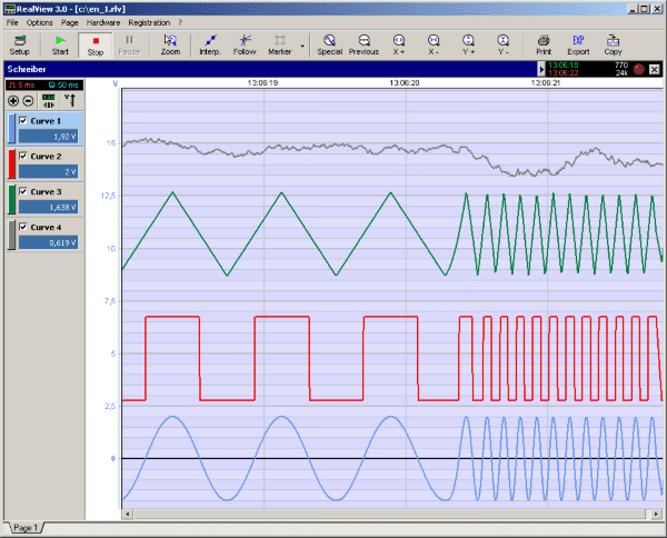
RealView 2.0
RealView is a measurement application, which records and plots measured values from analogue hardware devices in real-time. Several curves can be plotted into a single diagram. Several diagrams can be arranged on one or more pages if necessary. Plot options...

Blanket internal measurement circuit disconnection
The internal disconnection circuit for a blanket operates on the principle of induction. It includes a wire approximately 2 cm in length that senses the proximity of a charged mains power source. When the sensing wire is close to the...
Lie Detector Circuit
This electronic lie detector circuit project will provide two readings: one for challenging questions posed to the subject and another to indicate their emotional state.
The electronic lie detector circuit operates on the principles of galvanic skin response (GSR) and heart...

Simple Lie Detector Circuit
The circuit employs a two-transistor direct-coupled oscillator, with its frequency determined by capacitor C1, resistor R2, and the skin resistance across the touch pads. Since C1 and R2 are fixed values, only the skin resistance can vary the sound produced...

Lie detector circuit
This is a false capture circuit or lie detector circuit. The basic principle is based on the resistance of human skin. While dry skin has a resistance of about 1 Megaohm.
The lie detector circuit utilizes the principle of galvanic skin...

Advances in Measurement & Sensor Tech
This issue features articles on various measurement and sensor-related embedded design projects. Readers are encouraged to attempt similar projects and share their results. Starting on page 14, Petre Tzvetanov Petrov describes a multilevel audible logical probe design. Petrov notes that...

ProfiLab-Expert 4.0
The ProfiLab-Expert software allows you to develop your own digital or analogue measuring technology projects. It doesn't matter if you want to create analogue measurements or digital controls - you can realize it all. And for all this you don't...

ictd92
The Mark III conductivity-temperature-depth (CTD) profiler has been an essential tool in modern physical oceanographic research. The MKIIIB CTD delivers high-quality oceanographic data when operated by skilled personnel and is frequently recalibrated. The Integrated CTD system was designed to achieve...

Digital-ProfiLab 4.0
Digital-ProfiLab was designed for measurement and control applications, combining features like circuit and logic simulation, front panel design, and hardware control to one powerful tool. Incoming signals from external devices may be processed and displayed. A circuit editor is used...