


Light Detector Circuit
#light detector
#photocell
#CMOS 4001
#variable resistor
#piezo buzzer
#latch circuit
#trigger circuit
#sensor

Description: Variable resistor R1 adjusts the light threshold at which the circuit triggers. R1's value is chosen to match the photocell's resistance at darkness. The circuit uses a CMOS 4001 IC. Gate U1a acts as the trigger, U1b and c form a latch. S1 resets the circuit. The output device may be a low power piezo buzzer.
The described circuit utilizes a variable resistor, R1, which plays a crucial role in setting the light sensitivity threshold for triggering the circuit. The value of R1 is carefully selected to correspond with the resistance of a photocell in low light conditions, ensuring that the circuit activates when ambient light falls below a certain level.
The core of the circuit is built around the CMOS 4001 integrated circuit, which contains four NAND gates. In this configuration, gate U1a functions as the primary trigger for the circuit. It receives input from the voltage divider formed by the photocell and R1. When the light level drops and the voltage at the input of U1a reaches a specified threshold, the gate outputs a high signal, initiating the triggering sequence.
Subsequently, gates U1b and U1c are employed to create a latch mechanism. This latch maintains the output state even after the initial triggering condition has ceased, allowing the circuit to remain activated until it is intentionally reset. The reset function is facilitated by switch S1, which, when closed, clears the latch and returns the circuit to its original state.
The output of the latch is connected to a low power piezo buzzer, which serves as the output device. When the circuit is triggered, the buzzer emits sound, providing an audible indication of the light level falling below the defined threshold. This arrangement is particularly useful in applications such as automatic lighting systems or alarms that respond to changes in ambient light. The entire circuit is designed to operate efficiently with low power consumption, making it suitable for battery-operated devices.Variable resistor R1 adjusts the light threshold at which the circuit triggers. R1`s value is chosen to match the photocells resistance at darkness. The circuit uses a CMOS 4001 IC. Gate U1a acts as the trigger, U1b and c form a latch. S1 resets the circuit. The output device may be a low power piezo buzzer.
The described circuit utilizes a variable resistor, R1, which plays a crucial role in setting the light sensitivity threshold for triggering the circuit. The value of R1 is carefully selected to correspond with the resistance of a photocell in low light conditions, ensuring that the circuit activates when ambient light falls below a certain level.
The core of the circuit is built around the CMOS 4001 integrated circuit, which contains four NAND gates. In this configuration, gate U1a functions as the primary trigger for the circuit. It receives input from the voltage divider formed by the photocell and R1. When the light level drops and the voltage at the input of U1a reaches a specified threshold, the gate outputs a high signal, initiating the triggering sequence.
Subsequently, gates U1b and U1c are employed to create a latch mechanism. This latch maintains the output state even after the initial triggering condition has ceased, allowing the circuit to remain activated until it is intentionally reset. The reset function is facilitated by switch S1, which, when closed, clears the latch and returns the circuit to its original state.
The output of the latch is connected to a low power piezo buzzer, which serves as the output device. When the circuit is triggered, the buzzer emits sound, providing an audible indication of the light level falling below the defined threshold. This arrangement is particularly useful in applications such as automatic lighting systems or alarms that respond to changes in ambient light. The entire circuit is designed to operate efficiently with low power consumption, making it suitable for battery-operated devices.Variable resistor R1 adjusts the light threshold at which the circuit triggers. R1`s value is chosen to match the photocells resistance at darkness. The circuit uses a CMOS 4001 IC. Gate U1a acts as the trigger, U1b and c form a latch. S1 resets the circuit. The output device may be a low power piezo buzzer.
8PhotoNonInverting
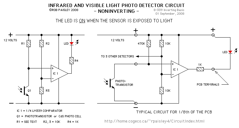
The circuit described is a visible and infrared light detector circuit board featuring eight detectors. The active components of this circuit are LM339 voltage comparators. These detectors can be integrated into other light detection circuits available on this site, including...

Photocell power supply (MAX630)
This circuit provides a regulated output of either 4.8 V or 7.2 V at a current of 15 mA, utilizing a 3 V input derived from a bank of photocells. Resistor R1 should be set to 453 kΩ for a...

Trigger Circuit Controls Stop-Motion Camera System
This version of the trigger circuit for the stop-motion camera system utilizes an electret microphone for sonic input, although it can be replaced with an LED and photodiode pair for optical triggering. A recent home-built project involved constructing a stop-motion...

Automatic Room light Control With Bi Directional Visitor Counter
The objective of this project is to create a controller-based model that counts the number of individuals entering a specific room and activates the lighting accordingly. This is achieved through the use of sensors that detect the current number of...

8 Photo-Detector Circuit Board
The circuit on this page is for a simple light detector circuit board that has 8 detectors that can be used with visible or infrared light systems. The detectors use LM339 voltage comparators as the active element. Phototransistors or CdS...
Scoobas Solution Sensing Tactic
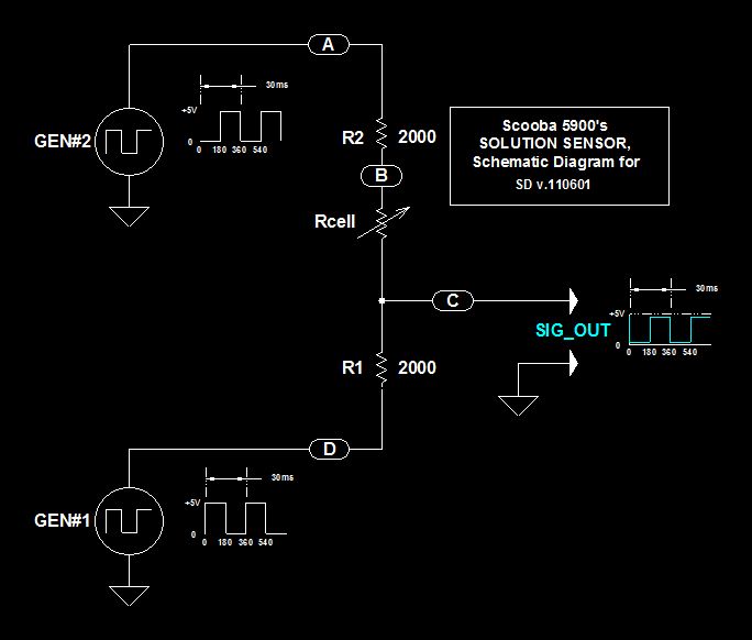
This document serves multiple purposes, primarily to document the methods employed by a Scooba robot to detect: a) the presence of an acceptable cleaning solution being delivered to its pump, and b) the excess presence of used solution collected off...

model train detector using photocell
This photocell is best mounted at tie level between the rails. The variable resistor adjusts the sensitivity of the circuit. This circuit can be powered by either 6 or 12 volts - BE SURE to use the proper relay; More:...
8 Photo-Detector Circuit Board
The circuit on this page is for a simple light detector circuit board that has 8 detectors that can be used with visible or infrared light systems. The detectors use LM339 voltage comparators as the active element. Phototransistors or CdS...
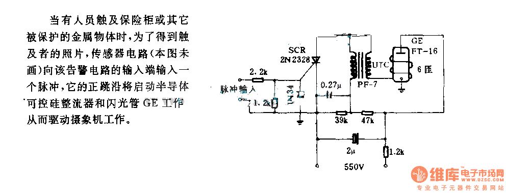
The alarm circuit diagram for safety box and other metal objects
When an individual touches the safety box or other protected metal objects, the sensor circuit generates a pulse to the alarm circuit. The positive edge of this pulse activates the semiconductor and thyristor flash GE, subsequently triggering the camera to...