


Light Meter Circuit

Description: The outputs from the comparators will transition, in sequence, from high to low as the input voltage exceeds the reference voltage applied to each comparator. The output LEDs will activate sequentially as the voltage increases. The inverting inputs of the comparators are connected in common to the collector of photo-transistor Q1. When Q1 is illuminated, its collector-emitter junction conducts, placing all the inverting inputs within a few millivolts of ground. For most settings of R1, each of the four reference voltages exceeds this value. Consequently, when Q1 is illuminated, the output from each comparator is high, and its corresponding indicator LED remains off.
The described circuit utilizes a series of comparators to monitor an input voltage against predetermined reference voltages. The operation of the circuit is contingent upon the illumination of a photo-transistor, Q1, which serves as a light-sensitive switch. When Q1 is exposed to light, it conducts, effectively grounding the inverting inputs of the comparators. This condition ensures that the output of each comparator remains high, resulting in the associated indicator LEDs being turned off.
As the input voltage rises and surpasses the reference voltages set for each comparator, the outputs will sequentially transition from high to low. This behavior is indicative of a voltage comparator configuration where the output state changes based on the relationship between the input voltage and the reference voltage. The sequential nature of the output allows for a visual indication of the voltage level through the activation of the LEDs.
The resistors, particularly R1, play a crucial role in setting the reference voltages for the comparators. The values of these resistors must be carefully selected to ensure that the reference voltages are appropriate for the desired input voltage range. The design should also consider the characteristics of the photo-transistor, including its response time and sensitivity to light, to ensure reliable operation in varying lighting conditions.
In summary, this circuit effectively utilizes a photo-transistor and voltage comparators to provide a visual representation of voltage levels through LED indicators, enabling straightforward monitoring of input voltage variations. The outputs from the comparators will swing, in sequence, from high to low as the input voltage rises above the reference voltage applied to each comparator. The output LEDs will then switch on in sequence as the voltage rises. The inverting inputs of the comparators are connected in common to the collector of photo-transistor Ql.
When Ql is illuminated, its collec-tor-emitter junction conducts, thereby placing all the inverting inputs within a few millivolts of ground. For most settings of Rl, each of the four reference voltages exceeds the value. Therefore, when Ql is illuminated, the output from each comparator is high and its respective indicator LED is off.
The described circuit utilizes a series of comparators to monitor an input voltage against predetermined reference voltages. The operation of the circuit is contingent upon the illumination of a photo-transistor, Q1, which serves as a light-sensitive switch. When Q1 is exposed to light, it conducts, effectively grounding the inverting inputs of the comparators. This condition ensures that the output of each comparator remains high, resulting in the associated indicator LEDs being turned off.
As the input voltage rises and surpasses the reference voltages set for each comparator, the outputs will sequentially transition from high to low. This behavior is indicative of a voltage comparator configuration where the output state changes based on the relationship between the input voltage and the reference voltage. The sequential nature of the output allows for a visual indication of the voltage level through the activation of the LEDs.
The resistors, particularly R1, play a crucial role in setting the reference voltages for the comparators. The values of these resistors must be carefully selected to ensure that the reference voltages are appropriate for the desired input voltage range. The design should also consider the characteristics of the photo-transistor, including its response time and sensitivity to light, to ensure reliable operation in varying lighting conditions.
In summary, this circuit effectively utilizes a photo-transistor and voltage comparators to provide a visual representation of voltage levels through LED indicators, enabling straightforward monitoring of input voltage variations. The outputs from the comparators will swing, in sequence, from high to low as the input voltage rises above the reference voltage applied to each comparator. The output LEDs will then switch on in sequence as the voltage rises. The inverting inputs of the comparators are connected in common to the collector of photo-transistor Ql.
When Ql is illuminated, its collec-tor-emitter junction conducts, thereby placing all the inverting inputs within a few millivolts of ground. For most settings of Rl, each of the four reference voltages exceeds the value. Therefore, when Ql is illuminated, the output from each comparator is high and its respective indicator LED is off.

Automatic White-LED Garden Light
This white LED driver circuit is suitable for garden lighting applications. It automatically activates the LED at night and operates from a single 1.2V NiCad cell, which is recharged by a solar cell during the day. The prototype utilized the...
Six LED Stereo VU Display
The following circuit is a six LED stereo VU display diagram that is constructed using the Dot/Bar Display Driver IC LM3915. This VU display should be connected before the amplifier module circuit. It can be connected at the pre-amp output,...

Knightrider lights for model cars
This circuit operates six LEDs in a "Knightrider scanner mode." The power consumption is primarily influenced by the type of LEDs utilized, especially when employing a 7555 (CMOS version of the 555 timer). Caution is advised when working with electricity,...

Night light Wake up Alarm Combo circuit
A nightlight combined with a wake-up alarm has been developed. This nightlight incorporates six LEDs that activate when a photosensor detects low ambient light levels. Additionally, a buzzer plays a cheerful tune when ambient light levels increase again. The system...

8x8x8 LED Cube
A total of 512 functional LEDs is required for the lattice assembly. These LEDs must be stable and bright. This section outlines the process for identifying faulty LEDs among the usable ones. Often, there are defective LEDs, particularly when purchased...

Light control automatic energy-saving LED lights circuit
The circuit is depicted in Figure 1, while the electrical schematic diagram is presented in Figure 2. The AC voltage of 220V is reduced by components C3 and R3. The diodes VD1 and VD2 rectify the voltage, and capacitors C2...

Using white LEDs
The yellow LEDs are on a small PCB, which are easy to remove. On the PCB there are 3 yellow LEDs and 4 diodes. Pictures of the PCB can be seen here: Top-side - Bottom-side. The schematic is as follows:...

light up pumpkin
The concept involves placing a pair of yellow LEDs inside a pumpkin, combined with a photo sensor that activates the lights at night. The circuit is simple, utilizing minimal components. Two schematics are provided on the project site, with a...
28 LED Clock schematic
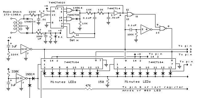
In the circuit below, 60 individual LEDs are used to indicate the minutes of a clock and 12 LEDs indicate hours. The power supply and time base circuitry is the same as described in the 28 LED clock circuit above....