


Light Sensor Circuit Using Op Amp 741

Description: This is a light sensor circuit designed to detect darkness, utilizing the op-amp 741 integrated circuit as the primary control element. The circuit is straightforward and specifically designed to sense light during nighttime. The light detection is accomplished using a Light Dependent Resistor (LDR). Under normal lighting conditions, the LDR exhibits high resistance, resulting in pin 2 of the op-amp being low. When light strikes the LDR, its resistance decreases to a few hundred ohms, causing pin 2 to go high. This change biases the base of transistor Q1 through pin 6 and resistor R4, subsequently activating the relay. A trimmer potentiometer (P1) along with two 470-ohm resistors (R2 and R3) forms a voltage divider to adjust the sensitivity of the circuit. To reverse the action of the sensor to detect darkness instead of light, the positions of the LDR and resistor R1 should be swapped. If the relay exhibits chattering, a hysteresis effect can be introduced by adding a resistor (R6) ranging from 100K to 1M ohms across pins 6 and 2 of the op-amp; typically, a value between 100K and 330K is sufficient. The LDR used is a standard, general-purpose type. Diode D1 functions as a spark arrestor when the relay contacts open. The power supply for this circuit operates at 12 V DC.
The light sensor circuit operates effectively by leveraging the characteristics of the LDR and the op-amp. The LDR's resistance varies inversely with the intensity of light; as light levels drop, the resistance increases, which is critical for the functioning of this circuit. The op-amp 741 is configured in a comparator mode where it compares the voltage at pin 2 (connected to the LDR) with a reference voltage at pin 3. When the voltage at pin 2 exceeds the reference voltage, the output at pin 6 goes high, turning on the transistor Q1, which in turn activates the relay.
The inclusion of the trimmer potentiometer P1 allows for fine-tuning of the sensitivity, making it adaptable to different ambient light conditions. The use of resistors R2 and R3 in conjunction with P1 ensures that the voltage divider can be adjusted to set the threshold at which the sensor activates.
For applications requiring the reverse functionality—detecting darkness instead of light—the simple modification of swapping the LDR and resistor R1 allows for this. This flexibility makes the circuit versatile for various use cases, such as automatic streetlights or security lighting.
The addition of resistor R6 introduces hysteresis, which is essential in preventing the relay from rapidly switching on and off due to minor fluctuations in light levels. This is particularly useful in environments where light conditions may vary frequently, such as near streetlights or during twilight.
Diode D1 is crucial for protecting the circuit from voltage spikes generated when the relay contacts open, ensuring the longevity and reliability of the circuit components. The overall design operates on a 12 V DC power supply, making it suitable for integration into various electronic systems requiring low-voltage operation.This is a one of the light sensor. This circuit is a dark sensor that is based on op amp 741 IC as main control. This circuit is a simple design for sensor the light at the night. This is the figure of the circuit. For sensor the light is using LDR. Operation of the circuit is under normal conditions the resistance of the LDR is high, keeping pin 2 low. When light falls onto the LDR the resistance drops to a couple hundred ohms and triggers pin 2 high which biases the base of Q1 via pin 6 and R4 and in turn activates the relay. Trimmer pot P1 and the two 470 ohm resistors, R2 and R3, are a voltage divider to adjust for sensitivity.
If you want the action reversed (make it a dark sensor), change the positions of the LDR and R1. If the relay chatters, add a bit of hysteresis by adding a 100K to 1Meg-ohm resistor (R6) over pins 6 and 2 of the 741 op-amp, but in most cases 100K to 330K will do the job. The LDR is a regular, general purpose type. D1 serves as a spark-arrestor when the relay contacts open. This circuit power supply is using 12 V DC.
The light sensor circuit operates effectively by leveraging the characteristics of the LDR and the op-amp. The LDR's resistance varies inversely with the intensity of light; as light levels drop, the resistance increases, which is critical for the functioning of this circuit. The op-amp 741 is configured in a comparator mode where it compares the voltage at pin 2 (connected to the LDR) with a reference voltage at pin 3. When the voltage at pin 2 exceeds the reference voltage, the output at pin 6 goes high, turning on the transistor Q1, which in turn activates the relay.
The inclusion of the trimmer potentiometer P1 allows for fine-tuning of the sensitivity, making it adaptable to different ambient light conditions. The use of resistors R2 and R3 in conjunction with P1 ensures that the voltage divider can be adjusted to set the threshold at which the sensor activates.
For applications requiring the reverse functionality—detecting darkness instead of light—the simple modification of swapping the LDR and resistor R1 allows for this. This flexibility makes the circuit versatile for various use cases, such as automatic streetlights or security lighting.
The addition of resistor R6 introduces hysteresis, which is essential in preventing the relay from rapidly switching on and off due to minor fluctuations in light levels. This is particularly useful in environments where light conditions may vary frequently, such as near streetlights or during twilight.
Diode D1 is crucial for protecting the circuit from voltage spikes generated when the relay contacts open, ensuring the longevity and reliability of the circuit components. The overall design operates on a 12 V DC power supply, making it suitable for integration into various electronic systems requiring low-voltage operation.This is a one of the light sensor. This circuit is a dark sensor that is based on op amp 741 IC as main control. This circuit is a simple design for sensor the light at the night. This is the figure of the circuit. For sensor the light is using LDR. Operation of the circuit is under normal conditions the resistance of the LDR is high, keeping pin 2 low. When light falls onto the LDR the resistance drops to a couple hundred ohms and triggers pin 2 high which biases the base of Q1 via pin 6 and R4 and in turn activates the relay. Trimmer pot P1 and the two 470 ohm resistors, R2 and R3, are a voltage divider to adjust for sensitivity.
If you want the action reversed (make it a dark sensor), change the positions of the LDR and R1. If the relay chatters, add a bit of hysteresis by adding a 100K to 1Meg-ohm resistor (R6) over pins 6 and 2 of the 741 op-amp, but in most cases 100K to 330K will do the job. The LDR is a regular, general purpose type. D1 serves as a spark-arrestor when the relay contacts open. This circuit power supply is using 12 V DC.

Simple Morning Alarm Circuit Using LDR and UM66
This article provides instructions for creating a light-sensitive morning alarm circuit. The circuit utilizes an LDR (Light Dependent Resistor) or photoresistor to detect morning light, which triggers the alarm section. When light is detected, the circuit produces a melodious tone....

Analog circuit enforces slow servo response
The all-analog circuit presented controls the rate at which a miniature turbojet engine can be throttled. Increasing or decreasing the throttle too quickly on a miniature turbojet engine, or any jet engine, can lead to quick failure in flight, causing...

automatic light controller circuit diagram
During nighttime, when no light falls on LDR1, it offers a high resistance at the base junction of transistor T1. Consequently, the bias is significantly reduced, and T1 does not conduct. This effectively removes the common terminal of IC1 from...
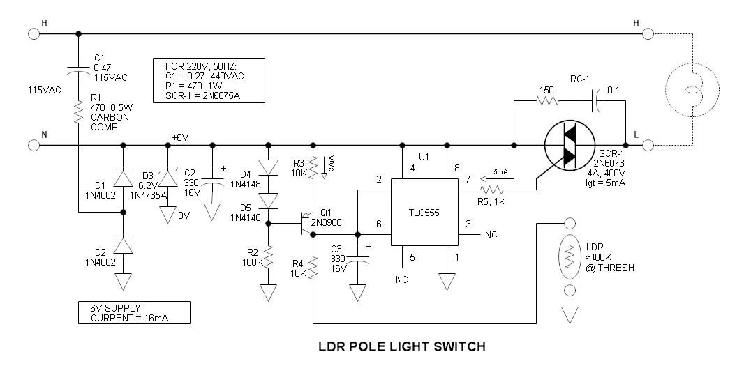
LDR Pole Light Switch
The vintage pole light, which is 62 years old, has traditionally been controlled by a timer, leading to ongoing frustration due to the need for adjustments with changing seasons. After accidentally knocking it over, an update was deemed necessary. The...

Light Sensitive Switch with LDR 2N2926
This circuit activates a warning when it becomes dark, functioning as a light-sensitive switch. The essential electronic components include the 2N2926 and AC128 transistors.
The described light-sensitive switch circuit is designed to detect ambient light levels and activate an output signal...

Light-Dependent Sensor For Multiple Inputs Circuit
This light-dependent sensor utilizes light-dependent resistors (LDRs) to detect the presence or absence of light. The alarm remains inactive as long as the light source illuminating the LDRs is constant. However, if the light is interrupted, the alarm is activated.
The...
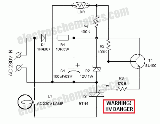
Automatic street light circuit
The circuit depicted will automatically switch ON and OFF at night and morning, respectively. In this circuit, R1 can be adjusted to change the sensitivity. The operation of the circuit is straightforward. The Light Dependent Resistor (LDR) exhibits very low...

Automatic light dimmer circuit
This is an automatic light dimmer circuit that eliminates the need for manual adjustment of light levels. It utilizes a Light Dependent Resistor (LDR) to detect ambient light conditions, which in turn controls a Triac to adjust the brightness of...

ldr engineer
LDR (Light Dependent Resistor) engineering involves creating various electronic circuits based on the principles of a simple light and dark sensor using transistors, the 555 timer IC, and the 741 operational amplifier IC. Among the various optical sensors, the light...