


Light Tracking Servo System
#light tracking
#servo
#photovoltaic
#PV array
#solar tracking
#sensor system
#automation
#energy efficiency

Description: Sun tracking systems significantly enhance the efficiency of photovoltaic (PV) arrays and are crucial for concentrated PV systems. This document discusses a light tracking servo model designed to simulate the movement of a PV array. A mathematical model is developed, and a qualitative comparison between the mathematical model and the actual physical model is conducted to demonstrate the dynamics of a light tracking servo system. An overall transfer function for a permanent magnet direct current (DC) motor is also developed. This topic is addressed as a separate case study in this course (refer to Case Study F). The motor transfer function is utilized in the formulation of an overall transfer function for the light tracking servo system. A computer simulation program in Matlab is employed to simulate the dynamics of the servo system using the overall transfer function. A qualitative analysis of the Matlab results is compared to the dynamics of the physical model to illustrate the significant dynamics of the system. The light tracking system comprises a permanent magnet DC motor, a directional light detecting circuit, and an amplifier to drive the motor. The physical configuration and a simple block diagram representation can be found in Figure 6E.1. Two photo-sensitive resistors are mounted on a triangular plexiglass support, ensuring that when the panel (the aluminum bar) is perpendicular to the light source, both resistors receive equal irradiance. When one resistor receives more light than the other, it indicates misalignment, resulting in an error voltage. This error voltage serves as a command to an amplifier circuit that drives the motor, aligning the panel perpendicular to the light source beam. The subsequent subsections provide a detailed description of the mechanical and electrical components of the model. To ensure the light tracking model is self-sufficient, a ±12 volt DC power supply is required for the electronic components. In typical solar applications, this DC power source is derived directly from PV panels or batteries charged by them. However, in this case, the DC power is generated by converting standard 110V AC power from a wall socket. The power supply is designed to accommodate a two-ampere load. Figure 6E.2 illustrates the electrical circuit responsible for the AC to DC power conversion. The circuit can be divided into four sections: transformation, rectification, filtering, and regulation. 1. Transformation is achieved by transformer T1, which steps down the 110 volts to two 15-volt peak AC sources. Ideally, the secondary voltage should be 20 volts peak; however, the lower voltage results in some ripple voltage on the output under load conditions of 1.5 amps or greater. The two secondaries are connected at one end to form the common ground of the DC source, which is distinct from the wall ground. 2. Rectification is performed by the diode bridge configuration B1. Although the configuration appears to be a bridge rectifier, it actually consists of two full-wave rectifiers. The right side of the bridge provides positive full-wave rectification, while the left side handles negative full-wave rectification. 3. Filtering is accomplished by capacitors C1 and C4, which smooth the rectified signal.
The light tracking servo system operates through a feedback loop that continuously adjusts the position of the PV array based on the intensity of light detected by the photo-sensitive resistors. The error voltage generated by the difference in light intensity is amplified and used to control the DC motor, ensuring that the PV array maintains optimal alignment with the light source throughout the day.
The mechanical design of the system is critical, as it must allow for smooth and precise movements of the PV array. The triangular plexiglass mount provides a stable platform for the photo-sensitive resistors, and the motor is securely fixed to allow for effective rotation of the array.
The electrical components are carefully chosen to ensure reliability and efficiency. The operational amplifier used in the amplifier circuit must have a suitable gain to ensure that even small differences in light intensity result in adequate motor response. Additionally, the capacitors used in the filtering stage must have appropriate voltage ratings and capacitance values to minimize ripple voltage and ensure stable DC output.
In summary, the integration of the mathematical model, the physical components, and the computer simulation in Matlab provides a comprehensive understanding of the dynamics of the light tracking servo system, facilitating the design and optimization of photovoltaic array systems for improved energy efficiency.Sun tracking systems are very effective in increasing the efficiency of photovoltaic (PV) arrays, and are essential for concentration PV systems. The following paper discusses a light tracking servo model which has been built to simulate the movement of a PV array.
A mathematical model is developed and a qualitative comparison of the mathematical model and the actual physical model is done to demonstrate the dynamics of a light tracking servo system. An overall transfer function for a permanent magnet direct current (dc) motor was also developed. This subject is treated as a separate Case Study in this course (see Case Study F). The motor transfer function is used in the development of an overall transfer function for the light tracking servo system. Using the overall transfer function, a computer simulation program within Matlab is used to simulate the dynamics of the servo system.
A qualitative analysis of the Matlab results and the dynamics of the working physical model are compared to clearly illustrate the important dynamics of the system. The light tracking system consists of a permanent magnet dc motor, a directional light detecting circuit, and an amplifier to drive the motor.
Refer to the model and to Fig. 6E. 1 for the physical configuration and a simple block diagram representation. Two photo sensitive resistors are physically mounted on a triangular plexiglass mount so that when the panel (the aluminum bar) is perpendicular to the light source, each receives an equal amount of irradiance. When one receives more light than the other, the panel is not aligned properly and an error voltage results.
The error voltage is used as a command to an amplifier circuit to drive the motor and align the panel to be perpendicular to the light source beam. The following subsections describe in detail the mechanical and electrical components of the model. To make the light tracking model self sufficient, a plus and minus 12 volt dc power supply is necessary for the electronic components.
In a typical solar application, this dc power source is obtained directly from the PV panels or batteries charged by the PV panels. However, in this case, the dc power is obtained by converting the standard 110 ac (alternating current) power from the wall socket.
For this application, the power supply is designed to handle a two ampere load. Figure 6E. 2 shows the electrical circuit which handles the conversion of ac to dc power. The circuit can be divided into four sections; transformation, rectification, filtering, and regulation. 1. Transformation is accomplished by the transformer (T1) which steps down the 110 volts to two 15 volt peak ac sources.
In a properly designed circuit, the secondary voltage should be 20 volts peak. The lower voltage level causes some ripple voltage on the output under load conditions of 1. 5 amp or greater. The two secondaries are tied together at one end to form the common ground of the dc source. This common ground is not the same as the ground from the wall. 2. Rectification is accomplished by the diode bridge configuration B1. Although the circuit seems to indicate a bridge rectifier, it is actually two full-wave rectifiers. The right side of the bridge provides positive full-wave rectification while the left side provides negative full-wave rectification. 3. Filtering is provided by capacitors C1 and C4 which level the rectified signal to
The light tracking servo system operates through a feedback loop that continuously adjusts the position of the PV array based on the intensity of light detected by the photo-sensitive resistors. The error voltage generated by the difference in light intensity is amplified and used to control the DC motor, ensuring that the PV array maintains optimal alignment with the light source throughout the day.
The mechanical design of the system is critical, as it must allow for smooth and precise movements of the PV array. The triangular plexiglass mount provides a stable platform for the photo-sensitive resistors, and the motor is securely fixed to allow for effective rotation of the array.
The electrical components are carefully chosen to ensure reliability and efficiency. The operational amplifier used in the amplifier circuit must have a suitable gain to ensure that even small differences in light intensity result in adequate motor response. Additionally, the capacitors used in the filtering stage must have appropriate voltage ratings and capacitance values to minimize ripple voltage and ensure stable DC output.
In summary, the integration of the mathematical model, the physical components, and the computer simulation in Matlab provides a comprehensive understanding of the dynamics of the light tracking servo system, facilitating the design and optimization of photovoltaic array systems for improved energy efficiency.Sun tracking systems are very effective in increasing the efficiency of photovoltaic (PV) arrays, and are essential for concentration PV systems. The following paper discusses a light tracking servo model which has been built to simulate the movement of a PV array.
A mathematical model is developed and a qualitative comparison of the mathematical model and the actual physical model is done to demonstrate the dynamics of a light tracking servo system. An overall transfer function for a permanent magnet direct current (dc) motor was also developed. This subject is treated as a separate Case Study in this course (see Case Study F). The motor transfer function is used in the development of an overall transfer function for the light tracking servo system. Using the overall transfer function, a computer simulation program within Matlab is used to simulate the dynamics of the servo system.
A qualitative analysis of the Matlab results and the dynamics of the working physical model are compared to clearly illustrate the important dynamics of the system. The light tracking system consists of a permanent magnet dc motor, a directional light detecting circuit, and an amplifier to drive the motor.
Refer to the model and to Fig. 6E. 1 for the physical configuration and a simple block diagram representation. Two photo sensitive resistors are physically mounted on a triangular plexiglass mount so that when the panel (the aluminum bar) is perpendicular to the light source, each receives an equal amount of irradiance. When one receives more light than the other, the panel is not aligned properly and an error voltage results.
The error voltage is used as a command to an amplifier circuit to drive the motor and align the panel to be perpendicular to the light source beam. The following subsections describe in detail the mechanical and electrical components of the model. To make the light tracking model self sufficient, a plus and minus 12 volt dc power supply is necessary for the electronic components.
In a typical solar application, this dc power source is obtained directly from the PV panels or batteries charged by the PV panels. However, in this case, the dc power is obtained by converting the standard 110 ac (alternating current) power from the wall socket.
For this application, the power supply is designed to handle a two ampere load. Figure 6E. 2 shows the electrical circuit which handles the conversion of ac to dc power. The circuit can be divided into four sections; transformation, rectification, filtering, and regulation. 1. Transformation is accomplished by the transformer (T1) which steps down the 110 volts to two 15 volt peak ac sources.
In a properly designed circuit, the secondary voltage should be 20 volts peak. The lower voltage level causes some ripple voltage on the output under load conditions of 1. 5 amp or greater. The two secondaries are tied together at one end to form the common ground of the dc source. This common ground is not the same as the ground from the wall. 2. Rectification is accomplished by the diode bridge configuration B1. Although the circuit seems to indicate a bridge rectifier, it is actually two full-wave rectifiers. The right side of the bridge provides positive full-wave rectification while the left side provides negative full-wave rectification. 3. Filtering is provided by capacitors C1 and C4 which level the rectified signal to

Solar automatic tracking controller circuit diagram
There are two types of solar automatic tracking controllers. One type utilizes a Schmitt trigger light control, which consists of a light sensor and a Schmitt trigger or monostable trigger. The second type employs two light sensors and two comparators...

SUN TRACKER HITEC SERVO ACTUATOR CONTROLLING ALIGNMENT SOLAR WING PANELS
The large servos shown alongside a Nokia 3310 mobile phone provide a reference for scale. The servo arms measure 12 cm in length, making them suitable for lifting a bank of solar panels. The local Model Aerodrome in Seaside Road,...

DC Servo
Additional experimentation has been conducted with the LTspice simulation of the Dxvideo preamplifier circuit that includes a DC servo. The .four command has been utilized within the simulation environment.
The LTspice simulation of the Dxvideo preamplifier circuit featuring a DC servo...

400 Hz SERVO AMPLIFIER
The signal from a synchro receiver or a variable resistive cam follower (potentiometer) is amplified by operational amplifier U1, with its output swing restricted by back-to-back zener diodes D3 and D4. This amplified signal is then fed into operational amplifiers...

Photovoltaic Light Sensors In Solar Tracker
The following circuit illustrates photovoltaic light sensors in a solar tracker. Features include accuracy, low cost, simplicity, and a single-axis electronic design.
The photovoltaic light sensor circuit is designed to optimize the alignment of solar panels with respect to the sun's...
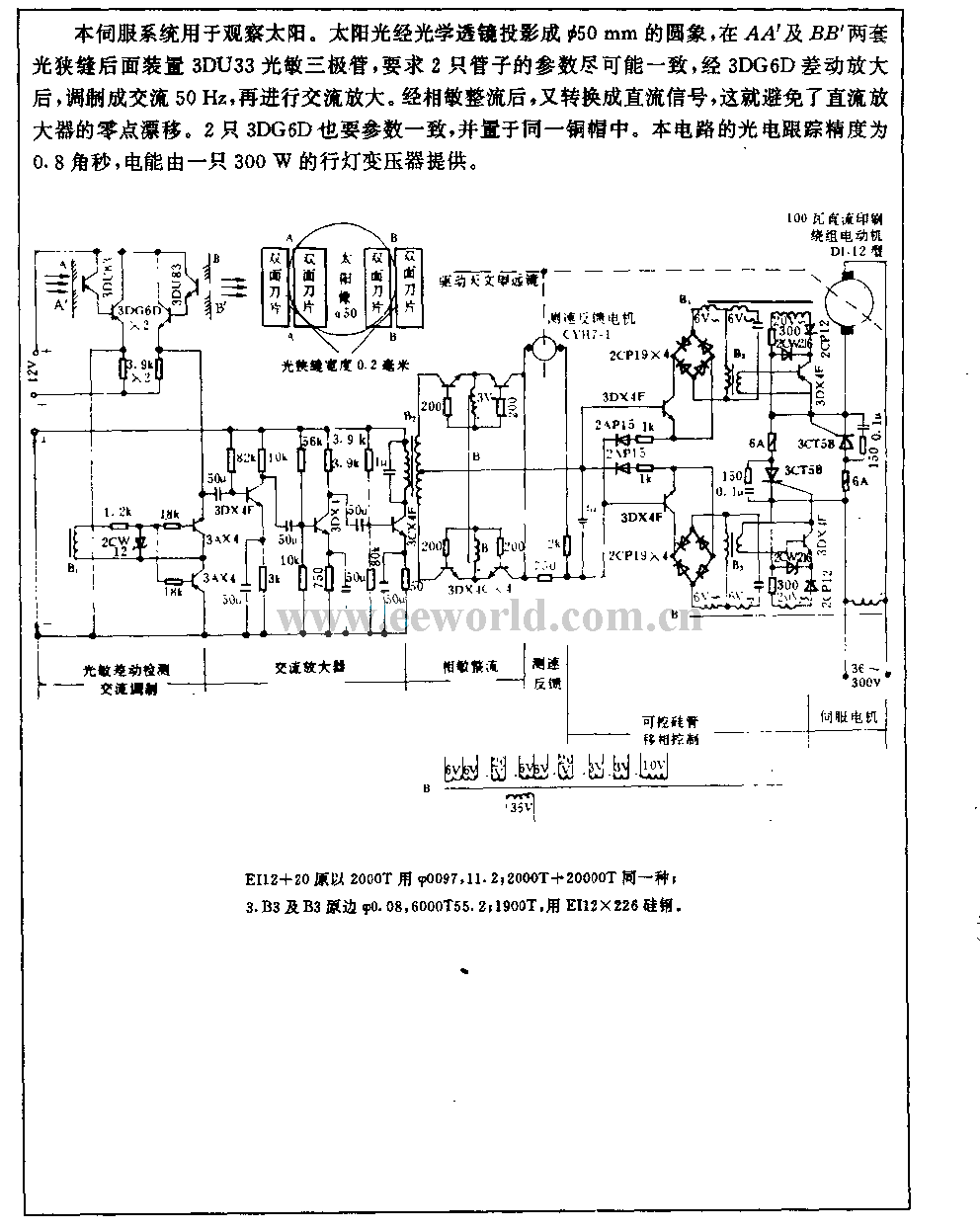
Tracking sun photoelectric servo circuit used in chromospheric telescope
This servo system is designed to track the sun. Sunshine is focused onto a 50mm round image using an optical lens, and a 3DU33 photosensitive transistor is positioned at the light slit of AA' and BB'. It is essential that...

Dr. Iguanas Vivarium
As the robot's battery voltage gradually decreases, the servo's center point begins to drift. Eventually, one or both servo motors may start to move even when they should be stationary. Additionally, servos are designed to maintain a position rather than...

Photovoltaic Power System and Wiring Module Interconnection
Photovoltaic (PV) technology involves the application of solar cells to convert sunlight directly into electricity. The provided manual on Photovoltaic Power Systems outlines practices in accordance with the 2005 National Electrical Code (NEC) relevant to PV power systems. This manual...

Servo-sensed-heater-protector
This circuit responds quickly enough to prevent damage from most overloads. Capacitor C1's input is connected to the output of the LT1088 servo circuit. If the LT1088 circuit's output exceeds the threshold at C1's other input, C1 trips, discharging the...