


Linear light-meter circuit
#light-meter
#op-amp
#light-level
#dc-indication
#sensitivity
#low-input-bias
#photodetector
#measurement

Description: This circuit employs a low-input-bias operational amplifier (op amp) to provide a stable DC indication of light levels. To decrease the sensitivity of the circuit to light, the resistor Rl can be reduced, although it should not be set below 100 kΩ. Additionally, the capacitor values in the circuit are selected to ensure a time constant that effectively filters out high-frequency light variations, which may occur due to sources such as fluorescent lights.
The described circuit utilizes a low-input-bias operational amplifier, which is advantageous for applications requiring minimal offset voltage and drift, ensuring accurate light level readings. The op amp is configured in a non-inverting configuration to amplify the input signal derived from a light-dependent resistor (LDR) or photodiode, which changes resistance based on the ambient light conditions.
The resistor Rl plays a crucial role in setting the gain of the circuit. By adjusting Rl, the sensitivity of the circuit can be tailored to specific light levels. However, it is important to maintain Rl at a minimum value of 100 kΩ to prevent excessive noise and instability in the output signal, which could compromise the accuracy of the light level indication.
Capacitors in the circuit are carefully selected to create a time constant that smooths out rapid fluctuations in the light signal. This filtering is essential in environments where light levels may vary quickly, such as under fluorescent lighting, which can produce flicker at higher frequencies. The time constant, determined by the product of the resistance and capacitance values, should be optimized to balance responsiveness to genuine changes in light levels while effectively rejecting high-frequency noise.
Overall, this circuit design effectively combines the precision of a low-input-bias op amp with carefully chosen resistive and capacitive components to deliver a reliable and stable DC output that reflects ambient light conditions, making it suitable for various applications in light sensing and control systems.This circuit uses a low-input-bias op amp to give a steady dc indication of light level. To reduce circuit sensitivity to light, Rl can be reduced, but should not be less than 100 K The capacitor values in the circuit are chosen to provide a time constant sufficient to filter high-frequency light variations that might arise, for example, from fluorescent lights.
The described circuit utilizes a low-input-bias operational amplifier, which is advantageous for applications requiring minimal offset voltage and drift, ensuring accurate light level readings. The op amp is configured in a non-inverting configuration to amplify the input signal derived from a light-dependent resistor (LDR) or photodiode, which changes resistance based on the ambient light conditions.
The resistor Rl plays a crucial role in setting the gain of the circuit. By adjusting Rl, the sensitivity of the circuit can be tailored to specific light levels. However, it is important to maintain Rl at a minimum value of 100 kΩ to prevent excessive noise and instability in the output signal, which could compromise the accuracy of the light level indication.
Capacitors in the circuit are carefully selected to create a time constant that smooths out rapid fluctuations in the light signal. This filtering is essential in environments where light levels may vary quickly, such as under fluorescent lighting, which can produce flicker at higher frequencies. The time constant, determined by the product of the resistance and capacitance values, should be optimized to balance responsiveness to genuine changes in light levels while effectively rejecting high-frequency noise.
Overall, this circuit design effectively combines the precision of a low-input-bias op amp with carefully chosen resistive and capacitive components to deliver a reliable and stable DC output that reflects ambient light conditions, making it suitable for various applications in light sensing and control systems.This circuit uses a low-input-bias op amp to give a steady dc indication of light level. To reduce circuit sensitivity to light, Rl can be reduced, but should not be less than 100 K The capacitor values in the circuit are chosen to provide a time constant sufficient to filter high-frequency light variations that might arise, for example, from fluorescent lights.

Precision peakvoltage detector
The circuit employs negative feedback exclusively for positive signals. The inverting input receives feedback only when diode D1 is forward biased, which occurs solely with positive input signals. As the positive input signal increases, the output of the operational amplifier...

Automatic mooring light
The integrated circuit U1, which can be an LF351 or a 741 operational amplifier, functions as a comparator to regulate lighting. Resistors R2 and R3 establish a reference voltage of approximately 2.5 volts at pin 3 of U1. When light...

Voltage Controlled Voltage Source
The drawback of the circuit mentioned is that the operational amplifier (op-amp) supply is connected to the high voltage (HV) supply. Most op-amps are limited to approximately 30V for their supply voltage, which prevents the circuit from functioning with higher...
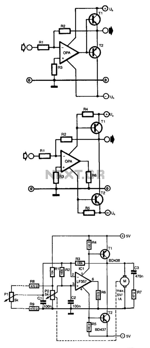
Op Amp Power Driver
Frequently, the output current of an operational amplifier is inadequate for applications such as driving a small motor or loudspeaker. This issue is typically resolved by adding an emitter follower to the circuit. However, this configuration does not allow the...

Op-Amp Application: Level Shifting Amplifier
In linear equipment design, it is sometimes necessary to take a voltage that is referenced to a certain DC level and generate an amplified output that is also referenced.
In linear circuit design, the process of amplifying a voltage that is...

Op-Amp Circuit: Difference Amplifier
This circuit is a difference amplifier. It functions as an inverting amplifier that enables the subtraction of two voltages, effectively performing a summation.
The difference amplifier is a fundamental circuit configuration in analog electronics, primarily used for amplifying the difference between...

3 Band Graphic Equalizer
This simple equalizer utilizes a single operational amplifier (op-amp) and provides three frequency ranges: low frequency, mid frequency, and high frequency. With the specified component values, it achieves approximately ±20 dB of gain or attenuation at frequencies of 50 Hz,...

Single-op-amp-clock
Capacitor C1 is charged through timing resistor R1 when the clock output is high. When C1 reaches the upper threshold voltage, the output signal decreases, and then C1 discharges through R1 until its voltage reaches the lower threshold point. When...

Accurate Low-Cost Square-Root Converter
This is a low-cost accurate square-root circuit. This circuit is used to provide a square-root function with good accuracy. The benefit of this circuit is its affordability and precision.
The low-cost accurate square-root circuit typically employs operational amplifiers (op-amps), resistors, and...