


LM1830 low level detector schematic circuit design
#low level detector
#LM1830
#audio indicator
#visual indicator
#500 Hz signal
#16V DC
#level sensing
#alarm

Description: The LM1830 low-level detector can utilize an audio indication (speaker) or a visual indicator (LED - light-emitting diode) that activates when the level is too low. This low-level detector circuit generates a 500 Hz audio signal when the level is low. The low-level detector requires a 16 V DC power supply, and the recipient must be made of metal, as the ground of the circuit needs to be connected to the recipient.
The LM1830 low-level detector is designed to monitor signal levels and provide an alert when those levels fall below a predetermined threshold. The circuit can be configured to drive either an audio output, typically a small speaker, or a visual output via an LED. When the input signal is detected to be below the set level, the LM1830 activates a 500 Hz audio tone, which serves as an audible alert, while simultaneously illuminating the LED to provide a visual cue.
The circuit requires a stable 16 V DC power supply to function correctly. The power supply should be able to deliver sufficient current to drive both the audio and visual indicators without distortion or failure. The inclusion of a metal recipient is crucial, as it serves as a ground reference for the circuit. This ground connection ensures that the circuit operates reliably and minimizes noise interference that could affect the detector's performance.
In terms of implementation, the circuit can be built using standard components that include resistors, capacitors, and the LM1830 integrated circuit. Proper selection of these components is essential to ensure the desired sensitivity and response time of the low-level detection. The output stage should be designed to handle the power requirements of the speaker or LED, with appropriate current-limiting resistors for the LED to prevent damage.
Overall, the LM1830 low-level detector circuit is a versatile solution for applications requiring reliable monitoring of signal levels, providing both audio and visual alerts to indicate low-level conditions effectively.This LM1830 low level detector can use an audio indication (speaker ) or a visual indicator (LED- light emitting diode ) that will light when the level is too low. This low level detector circuit will generate a 500 Hz audio signal when the level is low. This low level detector require a 16 V DC power supply and the recipient must be from some m etal, because you need to connect the ground of the circuit to the recipient.
The LM1830 low-level detector is designed to monitor signal levels and provide an alert when those levels fall below a predetermined threshold. The circuit can be configured to drive either an audio output, typically a small speaker, or a visual output via an LED. When the input signal is detected to be below the set level, the LM1830 activates a 500 Hz audio tone, which serves as an audible alert, while simultaneously illuminating the LED to provide a visual cue.
The circuit requires a stable 16 V DC power supply to function correctly. The power supply should be able to deliver sufficient current to drive both the audio and visual indicators without distortion or failure. The inclusion of a metal recipient is crucial, as it serves as a ground reference for the circuit. This ground connection ensures that the circuit operates reliably and minimizes noise interference that could affect the detector's performance.
In terms of implementation, the circuit can be built using standard components that include resistors, capacitors, and the LM1830 integrated circuit. Proper selection of these components is essential to ensure the desired sensitivity and response time of the low-level detection. The output stage should be designed to handle the power requirements of the speaker or LED, with appropriate current-limiting resistors for the LED to prevent damage.
Overall, the LM1830 low-level detector circuit is a versatile solution for applications requiring reliable monitoring of signal levels, providing both audio and visual alerts to indicate low-level conditions effectively.This LM1830 low level detector can use an audio indication (speaker ) or a visual indicator (LED- light emitting diode ) that will light when the level is too low. This low level detector circuit will generate a 500 Hz audio signal when the level is low. This low level detector require a 16 V DC power supply and the recipient must be from some m etal, because you need to connect the ground of the circuit to the recipient.
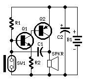
Personal Alarm
This circuit, enclosed in a small plastic box, can be placed into a bag or handbag. A small magnet is placed close to the reed switch and connected to the hand or the clothes of the person carrying the bag...
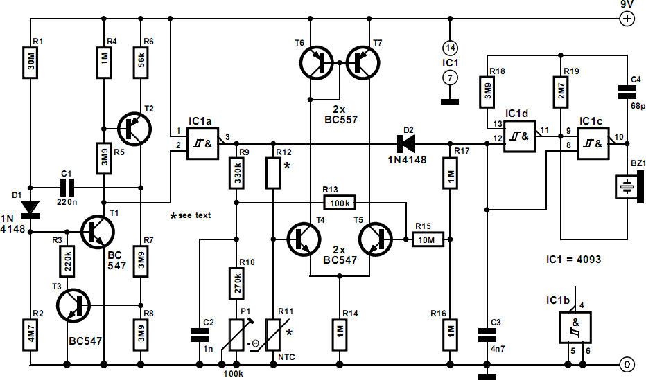
General-Purpose Alarm
The alarm can be utilized for various applications, including frost monitoring and room temperature monitoring. In its quiescent state, the circuit consumes only a few microamperes, allowing a 9 V dry battery (PP3, 6AM6, MN1604, 6LR61) to potentially last up...
Fridge Door Alarm Circuit
Emits a beep if the door remains open for more than 20 seconds. This circuit is housed in a compact enclosure and is positioned in the refrigerator near the lamp or the opening.
The described circuit functions as a door alarm...

Simple Alarm Circuit Keeps Wandering Children
The receiver circuit in Figure 1 activates an audio alarm when the transmitter (Figure 2) moves beyond a specified perimeter. The transmitter functions as a voltage-controlled oscillator, operating at approximately 915 MHz within the unlicensed ISM (industrial/scientific/medical) band. It features...

Single-Ic Alarm
With a single integrated circuit (IC), it is possible to construct a straightforward and dependable auto burglar alarm or a similar alarm system. Refer to (a) for the timing information related to the alarm circuit in (b). When leaving the...
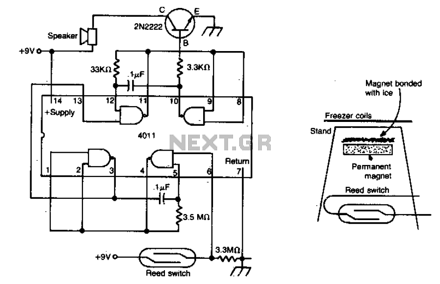
Freezer meltdown alarm
The meltdown consists of a magnet secured to a small stand by ice. A reed switch is positioned beneath the magnet. When the ice melts, the magnet drops onto the switch, closing it and completing the alarm circuit.
The described circuit...

Two HiJack Alarms
The first circuit was designed for the situation where a hijacker forces the driver from the vehicle. If a door is opened while the ignition is switched on - the circuit will trip. After a few minutes delay - when...

Simple lock circuit can alarm
The circuit operates as illustrated in Figure 5-2a. It includes an alarm switch (S). When switch S is pressed, relay K is activated, which closes two normally open contacts. This action triggers the alarm bells. The alarm continues to sound...
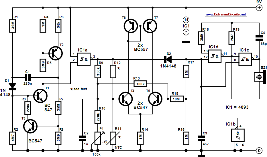
general purpose alarm
The alarm can be utilized for various applications, including frost monitoring and room temperature monitoring. In its quiescent state, the circuit consumes only a few microamperes, allowing a 9 V dry battery (PP3, 6AM6, MN1604, 6LR61) to potentially last up...