


Magnetometer
#magnetometer
#transistor
#VLF oscillator
#ferrite coil
#sensor
#magnetism detection
#rectifier
#dual-coil probe
#npn transistors

Description: The circuit employs two general-purpose NPN transistors, Q1 and Q2, along with a specially designed hand-wound dual-coil probe to detect magnetic fields. Q1, along with its associated components, forms a simple Very Low Frequency (VLF) oscillator circuit, with L1, C2, and C3 determining the oscillation frequency. The VLF signal captured by the pickup coil, L2, is filtered through capacitor C5 and subsequently rectified by diodes D1 and D2. The small DC output signal from the rectifier is directed to the base of Q2, which is configured as an emitter follower, and this output is then used to drive a 0-1 mA meter, M1.
The circuit operates by utilizing two NPN transistors, Q1 and Q2, where Q1 functions as the oscillator while Q2 serves as a signal amplifier. The oscillator circuit is critical for generating a VLF signal, which is influenced by the inductance of coil L1 and the capacitance values of capacitors C2 and C3. The specific frequency of oscillation can be adjusted by altering these component values, allowing for flexibility in the circuit's sensitivity to different magnetic field strengths.
The dual-coil probe, designed for this application, is capable of detecting variations in magnetic fields, which are then converted into an electrical signal. The first coil, L1, generates the VLF signal, while the second coil, L2, acts as the sensor that picks up the induced signal from the magnetic field. Capacitor C5 serves to smooth out the rectified output from the diodes D1 and D2, ensuring that the signal fed into Q2 is stable and suitable for amplification.
Q2, configured as an emitter follower, provides a high input impedance and low output impedance, which is ideal for driving the 0-1 mA meter, M1. This configuration allows for accurate representation of the detected magnetic field strength on the meter, with the output current proportional to the input signal from the rectifier. The overall design of the circuit emphasizes simplicity and effectiveness in detecting and measuring low-frequency magnetic fields, making it suitable for various applications in electronics and physics.The circuit uses two general-purpose npn transistors, Ql and Q2, and a special hand-wound, dual-coil probe ferrets out the magnetism. Ql and its associated components form a simple VLF oscillator circuit, with LI, C2, and C3 setting the frequency.
The VLF signal received by the pickup coil, L2, is passed through C5 and rectified by diodes Dl and D2. The small dc signal output from the rectifier is fed to the base of Q2 (configured as an emitter follower), which is then fed to a 0-1 mA meter, Ml.
The circuit operates by utilizing two NPN transistors, Q1 and Q2, where Q1 functions as the oscillator while Q2 serves as a signal amplifier. The oscillator circuit is critical for generating a VLF signal, which is influenced by the inductance of coil L1 and the capacitance values of capacitors C2 and C3. The specific frequency of oscillation can be adjusted by altering these component values, allowing for flexibility in the circuit's sensitivity to different magnetic field strengths.
The dual-coil probe, designed for this application, is capable of detecting variations in magnetic fields, which are then converted into an electrical signal. The first coil, L1, generates the VLF signal, while the second coil, L2, acts as the sensor that picks up the induced signal from the magnetic field. Capacitor C5 serves to smooth out the rectified output from the diodes D1 and D2, ensuring that the signal fed into Q2 is stable and suitable for amplification.
Q2, configured as an emitter follower, provides a high input impedance and low output impedance, which is ideal for driving the 0-1 mA meter, M1. This configuration allows for accurate representation of the detected magnetic field strength on the meter, with the output current proportional to the input signal from the rectifier. The overall design of the circuit emphasizes simplicity and effectiveness in detecting and measuring low-frequency magnetic fields, making it suitable for various applications in electronics and physics.The circuit uses two general-purpose npn transistors, Ql and Q2, and a special hand-wound, dual-coil probe ferrets out the magnetism. Ql and its associated components form a simple VLF oscillator circuit, with LI, C2, and C3 setting the frequency.
The VLF signal received by the pickup coil, L2, is passed through C5 and rectified by diodes Dl and D2. The small dc signal output from the rectifier is fed to the base of Q2 (configured as an emitter follower), which is then fed to a 0-1 mA meter, Ml.

microcontroller Why this transistor logic as switch is not working
The remote control of an RC car was modified by extending wires from the backward, forward, left, and right switches. Grounding any of these wires completes the circuit and sends a signal to the car. The intention is to close...

The NOT gate
The single-transistor inverter circuit discussed earlier is too simplistic for practical use as a gate. Real inverter circuits utilize multiple transistors to enhance voltage gain, ensuring that the final output transistor is either in full cutoff or full saturation, while...

Amplitude separation circuit diagram
Amplitude separation circuit. A typical amplitude separating circuit is composed of a transistor, capacitance C, and resistances RB and RC. The input signal is a composite video signal, typically with a peak-to-peak voltage of about 2V. The output signal is...
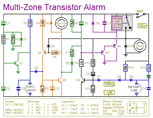
An Expandable Transistor Based Burglar Alarm
This transistor-based alarm system includes automatic exit and entry delays, a timed bell cut-off, and a system reset feature. In addition to the exit/entry zone, the basic alarm board is equipped with one instant zone, which is sufficient for many...

touch switch circuit with 3 transistors
This document describes a series of touch switches that utilize only three transistors. These touch-based transistor switches can activate a load simply by the user touching a metal plate. They are designed to directly switch a relay, enabling operation with...

SIMPLE DELAY TIMER FOR ONE MINUTE
A simple transistorized one-minute delay timer circuit. It does not include any complex or critical components. This circuit can generate a time delay of approximately one minute. When the switch (preferably a push-button type) is pressed, the LED turns on...

Leaky Transistor Buffer
The wah pedal operates before the amplifier but produces a low volume and a scratchy sound when the pedal is rocked back and forth. It functions correctly without the buffer. When placed in front of a Fuzz Face, no sound...

1N5401 3.0 AMP Silicon Rectifier
The schematic illustrates how +25V DC and -25V DC are generated to supply power to two stereo amplifiers. An 80VA power transformer with a 240V/36V center-tapped secondary winding is utilized. The secondary output of the transformer is rectified using four...

tone controller circuit diagram two transistor
The electrical schematic diagram presented below illustrates a simple two-transistor tone controller audio circuit, which is available for free download. This circuit is based on the well-known Baxandall tone control design. Variations in the values of the transistor components in...