


Making a Line Sensor using IR Receiver
#IR sensor
#line follower
#autonomous robot
#optical tracking
#floor surface
#sensor hardware
#robot navigation
#DIY sensor

Description: A line follower robot, abbreviated as LFR, is an autonomous robot designed to optically follow a line drawn on the floor. This involves the robot moving along an arbitrary line using a component known as a line sensor. A line sensor can be constructed using a low-cost infrared (IR) transmitter and receiver pair. The IR transmitter emits infrared radiation, which is detected by the receiver. To effectively create a line follower robot, multiple sensor units are combined, typically three or five, to form a line sensor array. The assembly process requires a small piece of veroboard (general-purpose PCB).
The circuit diagram provided on the website is unclear and difficult to read. A request has been made for a clearer copy of the main board circuit diagram. Additionally, there are comments regarding the limitations of the website's image size, which restricts the amount of detail that can be displayed.
A line follower robot operates through the use of an array of line sensors that detect the contrast between the line and the surface below. Each sensor unit typically consists of an infrared LED (transmitter) and a photodiode or phototransistor (receiver). When the infrared light emitted by the LED reflects off the surface, the receiver detects the intensity of the reflected light. If the sensor is over the line, the reflected light will be less intense than when it is over the surrounding surface, allowing the robot to determine its position relative to the line.
The control system of the line follower robot is generally implemented using a microcontroller, which processes the signals from the line sensors. Based on the sensor readings, the microcontroller adjusts the movement of the robot by controlling its motors. For example, if the left sensor detects the line while the right sensor does not, the microcontroller may command the right motor to speed up, guiding the robot back to the line.
Power for the robot is typically supplied by a battery pack, which should be chosen based on the voltage and current requirements of the motors and the microcontroller. The overall design can be enhanced with additional features such as speed control, obstacle avoidance, and more advanced navigation algorithms.
In constructing the robot, the use of a veroboard allows for easy prototyping and modification of the circuit. Components such as resistors, capacitors, and driver circuits may be added to improve performance and reliability. Proper soldering techniques and layout considerations are essential to ensure a functional and durable circuit.
For users seeking further information or assistance, it is advisable to consult detailed schematics and assembly instructions, which should ideally be provided in high-resolution formats for clarity.A line follower robot, or a LFR in short, is a simple autonomous robot that optically tracks a line made on the surface of the floor. That means you have an arbitrary line drawn on the floor and the robot tracks it by moving right along it!
The line is sensed using a piece of hardware called a line sensor. A line sensor can be easily made using a low cost IR Rx/Tx pair. The IR Rx emmits IR radiation and the Rx helps in receiving the waves. See the figure below for working of line sensor. Actually a group of such sensor units as described above is required to make a line follower robot. We generally use 3 or 5 such sensor unit to make a line sensor array. The complete steps are described below. You need small piece of veroboard (general purpose PCB). Recently, I purchased LFR from you to demonstrate to my kids. The circuit diagram given in your web site is faint so not readable. Could you kindly send me cleary copy of the circuit diagam of main board Thank you very much in advance. It is so because you were too fast in asking. Just click on the image it will enlarge. Today I am feeling pity that even after giving so much info, also I have to teach user please click here, click there too !
People quickly find faults in others NOT in their selves. On web site their is only a space for 500pixel wide image so it cannot contain more data than that, you need to click the image to download larger version. Its common sense.
The circuit diagram provided on the website is unclear and difficult to read. A request has been made for a clearer copy of the main board circuit diagram. Additionally, there are comments regarding the limitations of the website's image size, which restricts the amount of detail that can be displayed.
A line follower robot operates through the use of an array of line sensors that detect the contrast between the line and the surface below. Each sensor unit typically consists of an infrared LED (transmitter) and a photodiode or phototransistor (receiver). When the infrared light emitted by the LED reflects off the surface, the receiver detects the intensity of the reflected light. If the sensor is over the line, the reflected light will be less intense than when it is over the surrounding surface, allowing the robot to determine its position relative to the line.
The control system of the line follower robot is generally implemented using a microcontroller, which processes the signals from the line sensors. Based on the sensor readings, the microcontroller adjusts the movement of the robot by controlling its motors. For example, if the left sensor detects the line while the right sensor does not, the microcontroller may command the right motor to speed up, guiding the robot back to the line.
Power for the robot is typically supplied by a battery pack, which should be chosen based on the voltage and current requirements of the motors and the microcontroller. The overall design can be enhanced with additional features such as speed control, obstacle avoidance, and more advanced navigation algorithms.
In constructing the robot, the use of a veroboard allows for easy prototyping and modification of the circuit. Components such as resistors, capacitors, and driver circuits may be added to improve performance and reliability. Proper soldering techniques and layout considerations are essential to ensure a functional and durable circuit.
For users seeking further information or assistance, it is advisable to consult detailed schematics and assembly instructions, which should ideally be provided in high-resolution formats for clarity.A line follower robot, or a LFR in short, is a simple autonomous robot that optically tracks a line made on the surface of the floor. That means you have an arbitrary line drawn on the floor and the robot tracks it by moving right along it!
The line is sensed using a piece of hardware called a line sensor. A line sensor can be easily made using a low cost IR Rx/Tx pair. The IR Rx emmits IR radiation and the Rx helps in receiving the waves. See the figure below for working of line sensor. Actually a group of such sensor units as described above is required to make a line follower robot. We generally use 3 or 5 such sensor unit to make a line sensor array. The complete steps are described below. You need small piece of veroboard (general purpose PCB). Recently, I purchased LFR from you to demonstrate to my kids. The circuit diagram given in your web site is faint so not readable. Could you kindly send me cleary copy of the circuit diagam of main board Thank you very much in advance. It is so because you were too fast in asking. Just click on the image it will enlarge. Today I am feeling pity that even after giving so much info, also I have to teach user please click here, click there too !
People quickly find faults in others NOT in their selves. On web site their is only a space for 500pixel wide image so it cannot contain more data than that, you need to click the image to download larger version. Its common sense.

ir sensors from scratch line follower
To achieve an optimal voltage swing, the resistance value of R1 must be selected with precision. The sensor resistance, Rsensor, equals a when there is no light exposure and b when light is present. The voltage difference between these two...
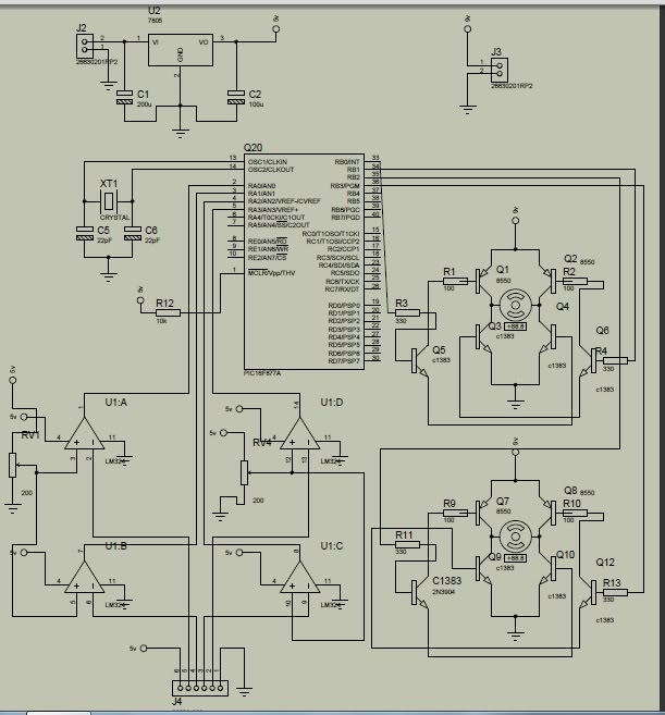
line follower mobile robot
This is a microcontroller hobby project featuring a line-following mobile robot named "Cruddy." The name reflects the somewhat messy structure of the robot. As a first-time builder, the soldering skills may not be fully developed. The chassis was sourced from...
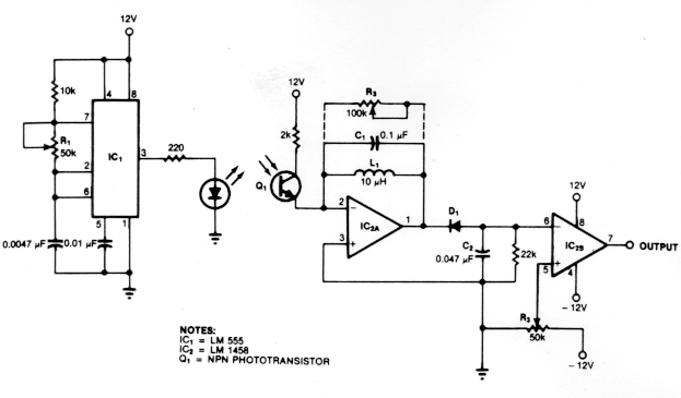
active ir motion detector
The circuit illustrates the operation of an ultrasonic motion detector, which consists of two transducers: one that emits ultrasonic waves and another that detects reflections from various objects in the vicinity. When no objects are in motion, the reflected waves...

ir remote control tester
While developing an infrared (IR) extender circuit, a method was required to measure the relative intensities of different infrared light sources. This circuit is the culmination of that research. It utilizes a photodiode, specifically the SFH2030, as the infrared sensor....

LINUSBot - Line Follower Robot using Arduino
If the robot is positioned on the black line, it will continue moving forward. However, if it veers off the line and enters a white area, it will assess whether to correct its path to the left or right, allowing...

simple line follower
When no light is incident on the diode, it exhibits high impedance (resistance). In contrast, when light strikes the diode, its resistance decreases significantly, approaching a short circuit condition. In the absence of any object in front of the sensor,...

analog line follower robot
Line follower robots are commonly designed to follow a specific path on a track. Typically, these robots are controlled by microcontrollers; however, this article discusses a line follower robot designed without using a microcontroller. The assembly consists of three main...
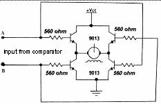
Analog Line Follower Robot
A line follower robot is designed to follow a designated path on a track. Typically, this type of robot is managed by a microcontroller.
The line follower robot operates using a series of sensors, commonly infrared (IR) sensors, to detect the...
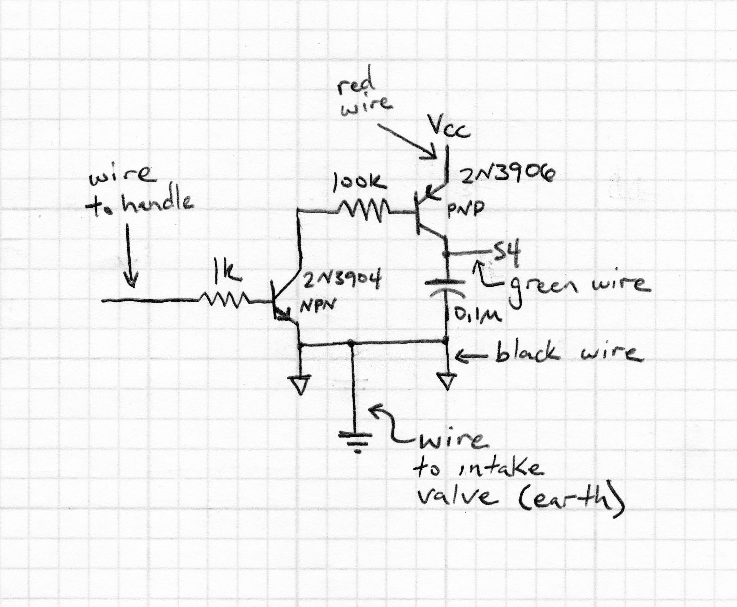
cruddy v 2 line follower mobile robot
This is the fifth iteration of a robot named Cruddy version 2. It functions as a line-following robot and features an improved circuit design, originally conceived by the designer. Notably, this project does not utilize a microcontroller; instead, it is...