


mass air flow maf sensor circuit
#mass air flow
#MAF sensor
#thermistor
#platinum hot wire
#electronic control circuit
#air flow measurement
#engine sensor
#voltage signal

Description: This design circuit is for a mass air flow (MAF) sensor. The MAF sensor converts the volume of air entering the engine into a voltage signal. The main components of the MAF sensor include a thermistor, a platinum hot wire, and an electronic control circuit. The thermistor measures the temperature of the incoming air. The hot wire is kept at a constant temperature relative to the thermistor by the electronic control circuit. An increase in airflow results in the hot wire losing heat more rapidly, prompting the electronic control circuitry to increase the current flowing through the wire.
The mass air flow sensor circuit plays a critical role in engine management systems by providing essential data for optimal fuel-air mixture calculations. The thermistor, which is a type of temperature sensor, is sensitive to variations in air temperature and provides real-time feedback to the electronic control unit (ECU). This feedback is crucial for adjusting fuel injection and ignition timing, thereby enhancing engine performance and efficiency.
The platinum hot wire, which serves as the sensing element, is heated to a predetermined temperature. When air flows over the wire, it cools down, and the rate of cooling is proportional to the mass flow of air. The electronic control circuit continuously monitors the temperature of the hot wire and compares it with the temperature reading from the thermistor. If the airflow increases, the hot wire cools more quickly, leading the control circuit to adjust the current supplied to the wire. This adjustment maintains the wire at its set temperature, ensuring accurate readings of the air mass flow.
In terms of circuit design, the MAF sensor typically includes an analog-to-digital converter (ADC) to translate the voltage signal into a digital format that the ECU can process. The circuit may also incorporate filtering and amplification stages to enhance signal integrity and reduce noise interference, ensuring reliable operation under varying environmental conditions.
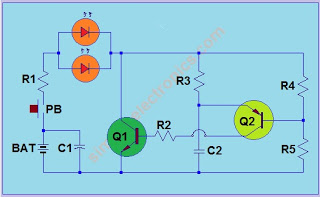
Overall, the mass air flow sensor circuit is a sophisticated assembly that integrates thermal dynamics with electronic control to optimize engine performance and efficiency, making it a vital component in modern automotive systems.This is a design circuit for mass air flow sensor circuit. The mass air flow sensors converts the amount of air drawn into the engine into a voltage signal. The primary components of the MAF sensor are thermistor, a platinum hot wire, and an electronic control circuit. The thermistor measures the temperature of the incoming air. This is the figure of the circuit; The hot wire is maintained at a constant temperature in relation to the thermistor by the electronic control circuit. An increase in air flow will cause the hot wire to lose heat faster and the electronic control circuitry will compensate by sending more current through the wire.
The mass air flow sensor circuit plays a critical role in engine management systems by providing essential data for optimal fuel-air mixture calculations. The thermistor, which is a type of temperature sensor, is sensitive to variations in air temperature and provides real-time feedback to the electronic control unit (ECU). This feedback is crucial for adjusting fuel injection and ignition timing, thereby enhancing engine performance and efficiency.
The platinum hot wire, which serves as the sensing element, is heated to a predetermined temperature. When air flows over the wire, it cools down, and the rate of cooling is proportional to the mass flow of air. The electronic control circuit continuously monitors the temperature of the hot wire and compares it with the temperature reading from the thermistor. If the airflow increases, the hot wire cools more quickly, leading the control circuit to adjust the current supplied to the wire. This adjustment maintains the wire at its set temperature, ensuring accurate readings of the air mass flow.
In terms of circuit design, the MAF sensor typically includes an analog-to-digital converter (ADC) to translate the voltage signal into a digital format that the ECU can process. The circuit may also incorporate filtering and amplification stages to enhance signal integrity and reduce noise interference, ensuring reliable operation under varying environmental conditions.
Overall, the mass air flow sensor circuit is a sophisticated assembly that integrates thermal dynamics with electronic control to optimize engine performance and efficiency, making it a vital component in modern automotive systems.This is a design circuit for mass air flow sensor circuit. The mass air flow sensors converts the amount of air drawn into the engine into a voltage signal. The primary components of the MAF sensor are thermistor, a platinum hot wire, and an electronic control circuit. The thermistor measures the temperature of the incoming air. This is the figure of the circuit; The hot wire is maintained at a constant temperature in relation to the thermistor by the electronic control circuit. An increase in air flow will cause the hot wire to lose heat faster and the electronic control circuitry will compensate by sending more current through the wire.

Car Ice ararm circuit
The circuit utilizes a thermistor and three sections of a LM3900 quad operational amplifier (op amp) integrated circuit. When the temperature decreases to 36°F, an LED indicator flashes approximately once per second. As the temperature continues to drop to 32°F,...
2/1/12 - 3/1/12
Initially, the thermistor (temperature-sensitive resistor) R1 has a resistance of 10 kilo-ohms at room temperature. As the temperature increases, its resistance decreases. When the resistance of R1 falls below the combined resistance of R2 and the potentiometer (POT), the comparator...

Thermistor lights lighting delay circuit
The circuit illustrated in Figure 2-49 is straightforward, featuring a cold Positive Temperature Coefficient (PTC) thermistor element. It utilizes the thermal resistance characteristics of the lamp to manage the delay time, which typically ranges from 10 to 30 seconds. To...
2/1/12 - 3/1/12
Initially, the thermistor (temperature-sensitive resistor) R1 has a resistance of 10 kilo-ohms at room temperature. As the temperature increases, its resistance decreases. When the resistance of R1 falls below the combined resistance of R2 and the potentiometer (POT), the comparator...
Fire Alarm Using Thermistor
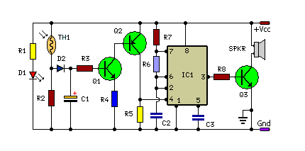
This is a small and simple unit that can be utilized for home security purposes. In this fire alarm circuit, a thermistor functions as the heat sensor. When the temperature increases...
The fire alarm circuit described utilizes a thermistor, a type...

FAST CLAMPl
The image 3-6 depicts a thermistor temperature or frequency conversion circuit. The resistance of thermistors changes linearly with temperature, allowing this change to be utilized in a voltage-controlled oscillator. In the circuit, operational amplifiers A1-A4 are current-type LM3900 models, while...

Frost AlarmCircuit Project
The thermistor utilized has a resistance of 15k ohms at 25 degrees Celsius and 45k ohms at 0 degrees Celsius. A suitable bead-type thermistor can be sourced from the Maplin catalogue. The inclusion of a 100k potentiometer enables this circuit...
temperature monitor
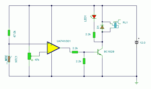
A thermistor placed in the specified position creates a heat-activated sensor. Variations in temperature will modify the output of the operational amplifier (op-amp), activating the relay and illuminating the LED. Interchanging the positions of the thermistor and the 47k resistor...

Thermistor electronic thermometer circuit diagram
The thermistor RT, along with resistors R1, R2, R3, and variable resistor RP1, creates a temperature measurement bridge. At a temperature of 20°C, the configuration of R1, R3, and the adjustment of RP1 enables the bridge to maintain balance. As...