


Measuring the differential pressure sensing bridge circuit diagram
#differential pressure
#sensing bridge
#feedback resistor
#zero adjustment
#span adjustment
#measurement
#instrumentation
#circuit diagram

Description: The circuit for zero and span adjustment consists of a feedback resistor network and a differential pressure sensing bridge measuring circuit. A constant current source, IO, represents the output current. The resistances of the four bridge arms are R1S, R3S, R4S, and R6S. As the measured positive pressure increases, the resistances of R1S and R6S decrease, while the resistances of R3S and R4S increase, leading to a negative increase in the output signal of the bridge, VBr. This VBr signal corresponds to the voltage deviation resulting from changes in the measured pressure. Due to the effects of the negative feedback resistor network in the measuring circuit, the VBr signal will remain very close to zero.
The zero and span adjustment circuit is designed to ensure the accurate measurement of differential pressure by utilizing a bridge configuration. The bridge circuit is composed of four resistors (R1S, R3S, R4S, and R6S) arranged in a Wheatstone bridge format, which allows for precise detection of small changes in resistance due to pressure variations. The constant current source (IO) provides a stable reference for the output current, ensuring consistent performance across varying conditions.
As the differential pressure increases, the resistances of R1S and R6S are affected by the pressure, resulting in a decrease in their values. Conversely, the resistances of R3S and R4S increase, creating an imbalance in the bridge. This imbalance generates a voltage output, VBr, which reflects the change in pressure. The output signal VBr is critical as it indicates the deviation from the expected voltage level corresponding to the measured pressure.
The feedback resistor network plays a pivotal role in stabilizing the output signal. By applying negative feedback, the circuit compensates for variations in the output signal, effectively driving VBr back towards zero. This feedback mechanism ensures that the system remains responsive while minimizing drift and noise, allowing for accurate readings in real-time applications.
In summary, the zero and span adjustment circuit is a sophisticated arrangement that leverages a feedback resistor network in conjunction with a differential pressure sensing bridge to maintain high accuracy and stability in pressure measurements. This design is essential for applications requiring precise pressure monitoring and control, such as in industrial automation, HVAC systems, and various scientific research scenarios.The figure is zero and span adjustment circuit includes a feedback resistor network and differential pressure sensing bridge measuring circuit. Constant current source IO represents the output current. Four bridge arm resistance is R1S, R3S, R4S and R6S. When the positive pressure measured increases, R1S and R6S resistance decreases, R3S and R4S resistance increases, the output signal of the bridge VBr negative increase. This VBr signal corresponding to the voltage deviation in the measured pressure change. After measuring circuit the negative feedback resistor network effect, VB r signal will remain very close to zero.
The zero and span adjustment circuit is designed to ensure the accurate measurement of differential pressure by utilizing a bridge configuration. The bridge circuit is composed of four resistors (R1S, R3S, R4S, and R6S) arranged in a Wheatstone bridge format, which allows for precise detection of small changes in resistance due to pressure variations. The constant current source (IO) provides a stable reference for the output current, ensuring consistent performance across varying conditions.
As the differential pressure increases, the resistances of R1S and R6S are affected by the pressure, resulting in a decrease in their values. Conversely, the resistances of R3S and R4S increase, creating an imbalance in the bridge. This imbalance generates a voltage output, VBr, which reflects the change in pressure. The output signal VBr is critical as it indicates the deviation from the expected voltage level corresponding to the measured pressure.
The feedback resistor network plays a pivotal role in stabilizing the output signal. By applying negative feedback, the circuit compensates for variations in the output signal, effectively driving VBr back towards zero. This feedback mechanism ensures that the system remains responsive while minimizing drift and noise, allowing for accurate readings in real-time applications.
In summary, the zero and span adjustment circuit is a sophisticated arrangement that leverages a feedback resistor network in conjunction with a differential pressure sensing bridge to maintain high accuracy and stability in pressure measurements. This design is essential for applications requiring precise pressure monitoring and control, such as in industrial automation, HVAC systems, and various scientific research scenarios.The figure is zero and span adjustment circuit includes a feedback resistor network and differential pressure sensing bridge measuring circuit. Constant current source IO represents the output current. Four bridge arm resistance is R1S, R3S, R4S and R6S. When the positive pressure measured increases, R1S and R6S resistance decreases, R3S and R4S resistance increases, the output signal of the bridge VBr negative increase. This VBr signal corresponding to the voltage deviation in the measured pressure change. After measuring circuit the negative feedback resistor network effect, VB r signal will remain very close to zero.

ProfiLab-Expert 4.0
The ProfiLab-Expert software allows you to develop your own digital or analogue measuring technology projects. It doesn't matter if you want to create analogue measurements or digital controls - you can realize it all. And for all this you don't...

Digital-ProfiLab 4.0
Digital-ProfiLab was designed for measurement and control applications, combining features like circuit and logic simulation, front panel design, and hardware control to one powerful tool. Incoming signals from external devices may be processed and displayed. A circuit editor is used...
Digital-ProfiLab 4.0
Digital-ProfiLab was designed for measurement and control applications, combining features like circuit and logic simulation, front panel design, and hardware control to one powerful tool. Incoming signals from external devices may be processed and displayed. A circuit editor is used...
ProfiLab-Expert 4.0
The ProfiLab-Expert software allows you to develop your own digital or analogue measuring technology projects. It doesn't matter if you want to create analogue measurements or digital controls - you can realize it all. And for all this you don't...

Instrumentation circuit
The mechanical chassis prototype, as illustrated in the accompanying image, was constructed using two materials: foam and aluminum. Foam was selected for its ease of manipulation, while aluminum was chosen for its excellent strength-to-weight ratio. The prototype features a rotary...
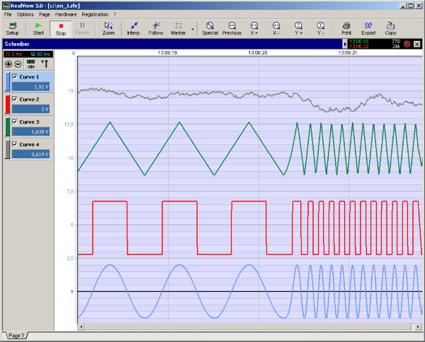
RealView 2.0
RealView is a measurement application, which records and plots measured values from analogue hardware devices in real-time. Several curves can be plotted into a single diagram. Several diagrams can be arranged on one or more pages if necessary. Plot options...

Blanket internal measurement circuit disconnection
The internal disconnection circuit for a blanket operates on the principle of induction. It includes a wire approximately 2 cm in length that senses the proximity of a charged mains power source. When the sensing wire is close to the...

Advances in Measurement & Sensor Tech
This issue features articles on various measurement and sensor-related embedded design projects. Readers are encouraged to attempt similar projects and share their results. Starting on page 14, Petre Tzvetanov Petrov describes a multilevel audible logical probe design. Petrov notes that...
RealView 2.0
RealView is a measurement application, which records and plots measured values from analogue hardware devices in real-time. Several curves can be plotted into a single diagram. Several diagrams can be arranged on one or more pages if necessary. Plot options...