


Micropower double ended limit detector
#voltage monitor
#limit detector
#low power
#CMOS
#NAND gate
#L144
#DC4011
#logical high
#logical low
#voltage threshold

Description: The detector utilizes three sections of an L144 and a DC4011 type CMOS NAND gate to create a very low power voltage monitor. If the input voltage, Vin, is above Vhigh or below Vlow, the output will be a logical high. The output will be low only when the input is within the specified limits.
The circuit employs four 1 megohm resistors, R1, R2, R3, and R4, which serve to convert the bipolar ±10V swing of the operational amplifiers to a 0 to 5V swing that is compatible with ground-referenced CMOS logic.
The primary function of this voltage monitor is to provide a reliable indication of whether the input voltage is within the predefined thresholds. The L144 sections act as voltage comparators, monitoring the input voltage against the set limits, Vhigh and Vlow. When Vin exceeds Vhigh, or falls below Vlow, the output of the NAND gate transitions to a logical high state, signaling that the monitored voltage is outside the acceptable range. Conversely, when Vin is within the specified limits, the output remains low.
The choice of using a CMOS NAND gate is significant due to its low power consumption characteristics, making it suitable for battery-operated devices or applications where power efficiency is critical. The resistors R1 through R4 play a crucial role in ensuring that the analog signals from the operational amplifiers are scaled down appropriately to avoid damage to the CMOS logic and to ensure accurate logical interpretation.
In summary, this voltage monitor circuit effectively combines the functionality of operational amplifiers and CMOS logic to provide a robust solution for monitoring voltage levels in various electronic applications, ensuring that the output accurately reflects the input voltage conditions.The detector uses three sections of an L144 and a DC4011 type CMOS NAND gate to make a very low power voltage monitor. If the input voltage, Vin, is above Vhigh or below Vlow, the output will be a logical high. If (and only if) the input is between the limits will the output be low
The circuit employs four 1 megohm resistors, R1, R2, R3, and R4, which serve to convert the bipolar ±10V swing of the operational amplifiers to a 0 to 5V swing that is compatible with ground-referenced CMOS logic.
The primary function of this voltage monitor is to provide a reliable indication of whether the input voltage is within the predefined thresholds. The L144 sections act as voltage comparators, monitoring the input voltage against the set limits, Vhigh and Vlow. When Vin exceeds Vhigh, or falls below Vlow, the output of the NAND gate transitions to a logical high state, signaling that the monitored voltage is outside the acceptable range. Conversely, when Vin is within the specified limits, the output remains low.
The choice of using a CMOS NAND gate is significant due to its low power consumption characteristics, making it suitable for battery-operated devices or applications where power efficiency is critical. The resistors R1 through R4 play a crucial role in ensuring that the analog signals from the operational amplifiers are scaled down appropriately to avoid damage to the CMOS logic and to ensure accurate logical interpretation.
In summary, this voltage monitor circuit effectively combines the functionality of operational amplifiers and CMOS logic to provide a robust solution for monitoring voltage levels in various electronic applications, ensuring that the output accurately reflects the input voltage conditions.The detector uses three sections of an L144 and a DC4011 type CMOS NAND gate to make a very low power voltage monitor. If the input voltage, Vin, is above Vhigh or below Vlow, the output will be a logical high. If (and only if) the input is between the limits will the output be low
The 1 megohm resistors Rl, R2, R3, and R4 translate the bipolar ±10V swing of the op amps to a 0 to LOV swing acceptable to the ground-referenced CMOS logic.

Two Interlocked Toggle Switches - Cmos 4013
This versatile circuit offers a selection of different switching modes. It can function as two entirely separate toggle switches, with each push button successively energizing and de-energizing its corresponding relay. Alternatively, the two switches can be interconnected with diodes to...

4093 Cmos Vfo Circuit
Two gates of a Quad 4093 are utilized in an astable multivibrator configuration. CI is a three-gang 365 pF variable capacitor with its sections connected in parallel. Additionally, S3 and S4 serve to switch in optional extra capacitors.
The described circuit...

Digital Inverter
The configuration involves connecting two FETs to create a CMOS digital inverter.
The CMOS (Complementary Metal-Oxide-Semiconductor) digital inverter is a fundamental building block in digital electronics, widely used in various applications such as logic gates, amplifiers, and memory circuits. This inverter...
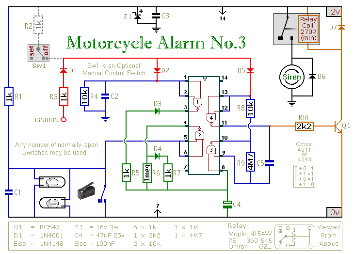
A Cmos Based Motorcycle Alarm circuit
This circuit provides an intermittent siren output with an automatic reset feature. It can be operated manually through a key-switch or a hidden switch, and it can also be configured to activate automatically when the ignition is turned off. By...

CMOS Pocketable Timekeeper
The CMOS Pocketable Timekeeper is a compact timekeeping circuit designed for portability. This circuit diagram illustrates the functionality of the CMOS Pocketable Timekeeper along with various advanced timer projects and electronic applications.
The CMOS Pocketable Timekeeper circuit utilizes complementary metal-oxide-semiconductor (CMOS)...

Single Cell Battery 1.5V 20dB Inverting Amplifier
This amplifier circuit exhibits a very low power consumption, with a total current draw of 675 nA. The output voltage swing is 300 mV peak-to-peak (pp) with a gain of 20.
The amplifier circuit is designed to operate with minimal power...

Cmos Pair 2-Mhz Crystal Oscillator
This circuit is a 2 MHz crystal oscillator utilizing a CMOS transistor pair. It is particularly suitable for applications in digital watches and clocks due to its low power consumption. The oscillator is constructed by connecting a CMOS transistor pair...

Simple circuit diagram repellent
A low-cost and straightforward repellent circuit can be utilized for deterring rats, mice, and other animals, as illustrated in the electronic figure below. The circuit employs a CMOS integrated circuit of type 4047, which functions as a relaxation oscillator. Its...
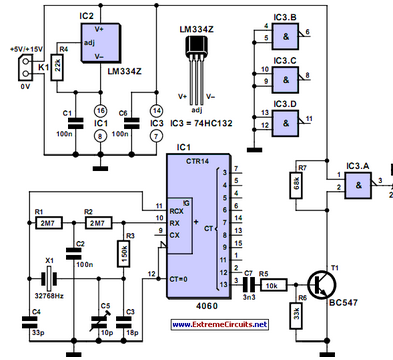
Thrifty 2Hz Clock
CMOS circuits are recognized for their low current consumption, which is especially significant for battery-powered applications. However, oscillators frequently face challenges related to...
CMOS (Complementary Metal-Oxide-Semiconductor) technology is widely utilized in the design of integrated circuits due to its advantageous characteristics,...