


Moisture Detector Circuit
#moisture detector
#transistor
#piezoelectric transducer
#oscillator
#alarm
#water sensor
#crystal-controlled
#sensor circuit
#audio alarm

Description: The moisture detector utilizes two transistors and a piezoelectric transducer to emit an alarm tone when water is detected. Transistor Q1 functions as a crystal-controlled oscillator, employing a portion of the piezoelectric transducer XDC, which consists of two piezoelectric crystal regions, as the crystal. The transducer is equipped with three separate leads: one connected to each crystal and the third serving as a common connection. The smaller internal crystal region determines the operational frequency, while the larger element is activated by Q1 (when biased on) to produce a loud tone output. To activate the PNP transistor Q1 (acting as an oscillator), the PNP transistor Q2 (functioning as a switch) must also be on. To achieve this with the standard biasing configuration, a resistor must be connected from the collector of Q2 to the base, providing a negative (-) bias to the base. The resistor utilized for this purpose is the water that needs to be detected. Consequently, when water contacts the probe, Q2 is turned on, which in turn activates Q1, resulting in the transducer emitting a loud sound.
The moisture detector circuit operates based on the interaction between two PNP transistors and a piezoelectric transducer, which is critical for sound generation. The first transistor, Q1, acts as a crystal-controlled oscillator, utilizing a segment of the piezoelectric transducer that is divided into two crystal regions. The smaller crystal region is specifically designed to set the frequency of the oscillator, while the larger region is responsible for generating the audible alarm tone when activated.
The piezoelectric transducer is configured with three leads: two leads are dedicated to the individual crystals, and the third lead serves as a common ground. This arrangement allows for efficient signal processing and sound production. When water is detected, it acts as a resistor in the circuit, effectively providing the necessary bias to turn on transistor Q2. This switching action is crucial, as Q2 must be in an active state to enable Q1 to function properly.
When water contacts the probe, the resistance changes, allowing current to flow from the collector of Q2 to its base. This negative bias energizes Q2, allowing it to conduct and subsequently energize Q1. Once Q1 is activated, it drives the larger piezoelectric crystal, resulting in the emission of a loud sound from the transducer. This sound serves as an alarm, indicating the presence of moisture.
The design of the moisture detector circuit emphasizes the importance of component interaction and biasing techniques in achieving reliable operation. The use of piezoelectric materials not only facilitates sound production but also enhances the sensitivity of the moisture detection mechanism. Overall, this circuit provides an effective solution for moisture detection applications, leveraging the properties of transistors and piezoelectric devices to create a functional alarm system. The moisture detector uses two transistors and a piezoelectric transducer to sound an alarm tone when water is present. Transistor Ql forms a crystal-controlled oscillator, using a portion of piezoelectric transducer XDCwhich contains two piezoelectric crystal regionsas the crystal.
The transducer has three separate leads. One lead goes to each of the crystals, and the third lead is common to both. The smaller internal crystal region sets the frequency of operation and the larger element is driven by Ql (when it is biased on) to provide the loud tone output. To turn the pnp transistor Ql (used as an oscillator) on pnp transistor Q2 (used here as a switch) must be on. To turn it on with the biasing that is normally connected, you would only need to connect a resistor from the collector of Q2 to the base, which gives the base a negative (-) bias.
The resistor used is the water that is to be detected. That turns Q2 on, which, in turn, turns on Ql. The result when water touches the probe is that the transducer emits a loud sound.
The moisture detector circuit operates based on the interaction between two PNP transistors and a piezoelectric transducer, which is critical for sound generation. The first transistor, Q1, acts as a crystal-controlled oscillator, utilizing a segment of the piezoelectric transducer that is divided into two crystal regions. The smaller crystal region is specifically designed to set the frequency of the oscillator, while the larger region is responsible for generating the audible alarm tone when activated.
The piezoelectric transducer is configured with three leads: two leads are dedicated to the individual crystals, and the third lead serves as a common ground. This arrangement allows for efficient signal processing and sound production. When water is detected, it acts as a resistor in the circuit, effectively providing the necessary bias to turn on transistor Q2. This switching action is crucial, as Q2 must be in an active state to enable Q1 to function properly.
When water contacts the probe, the resistance changes, allowing current to flow from the collector of Q2 to its base. This negative bias energizes Q2, allowing it to conduct and subsequently energize Q1. Once Q1 is activated, it drives the larger piezoelectric crystal, resulting in the emission of a loud sound from the transducer. This sound serves as an alarm, indicating the presence of moisture.
The design of the moisture detector circuit emphasizes the importance of component interaction and biasing techniques in achieving reliable operation. The use of piezoelectric materials not only facilitates sound production but also enhances the sensitivity of the moisture detection mechanism. Overall, this circuit provides an effective solution for moisture detection applications, leveraging the properties of transistors and piezoelectric devices to create a functional alarm system. The moisture detector uses two transistors and a piezoelectric transducer to sound an alarm tone when water is present. Transistor Ql forms a crystal-controlled oscillator, using a portion of piezoelectric transducer XDCwhich contains two piezoelectric crystal regionsas the crystal.
The transducer has three separate leads. One lead goes to each of the crystals, and the third lead is common to both. The smaller internal crystal region sets the frequency of operation and the larger element is driven by Ql (when it is biased on) to provide the loud tone output. To turn the pnp transistor Ql (used as an oscillator) on pnp transistor Q2 (used here as a switch) must be on. To turn it on with the biasing that is normally connected, you would only need to connect a resistor from the collector of Q2 to the base, which gives the base a negative (-) bias.
The resistor used is the water that is to be detected. That turns Q2 on, which, in turn, turns on Ql. The result when water touches the probe is that the transducer emits a loud sound.
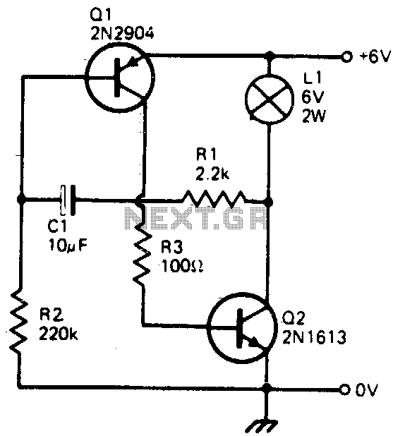
Transistorized flasher
This simple circuit will flash a 6-volt lamp at a rate determined by the size of capacitor C1. It is most economical on power as it only draws current when the lamp is on. When the lamp is off, both...

Easy-auto-alarm
Refer to (a) for the timing information related to the alarm circuit depicted in (b). When departing from the vehicle, the arming switch should be flipped, and the door closed to activate the device. The subsequent opening of an entrance...

Transistor Organ
This simple circuit can provide hours of enjoyment as you learn tunes, play duets or just make some really weird sounds by pushing all the buttons at once. You have probably seen this circuit before, it is fairly common. I...

Single Alarm Circuit
This is a single alarm circuit. The circuit includes automatic exit and entry delays, a timed bell cut-off, and a system reset. It has provisions for normally open and normally closed inputs.
The single alarm circuit is designed to provide security...

Multi-Zone Transistor-Based Intruder Alarm
This is a simple transistor-based burglar alarm circuit. Its features include automatic exit and entry delays, along with a timed bell cut-off and reset. It is designed to be used with standard types of normally-closed input devices such as magnetic...
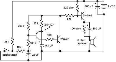
Emergency Siren Simulator
The core of the circuit is a two-transistor flasher, with frequency modulation applied to the base of the first transistor. When the pushbutton is pressed, the oscillation frequency increases to a peak, and upon releasing the button, the frequency decreases...

Very Low Distortion Oscillator
This oscillator utilizes a bridge circuit with an optoisolator functioning as a gain-control device. The resultant distortion can be maintained at 9 ppm (0.0009%) with appropriate adjustments.
The oscillator circuit described operates using a bridge configuration, which is a common approach...

A circuit diagram of the filter by the transistor
This article describes a band-pass filter circuit diagram utilizing transistors.
A band-pass filter is an essential electronic circuit that allows signals within a certain frequency range to pass while attenuating frequencies outside that range. The circuit typically consists of a combination...

Toy Motor Drivers
This is a reverse-engineered circuit diagram of a one-transistor circuit commonly used to drive permanent magnet DC motors in children's toys. This circuit typically employs the 625mW version of the widely used 8050 or 8550 transistor. It is important to...