


Moisture detector with pump controller
#moisture detector
#pump controller
#LM1830
#555 timer
#AC current
#hysteresis
#sensor probe
#liquid detection
#delay circuit
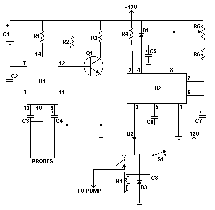
Description: This moisture detector with pump controller is built around the special purpose LM1830 IC. The LM1830 is designed to detect moisture by passing an AC current through a set of probes. An internal comparator compares the resistance of the probes to an internal reference. When the resistance between the probes is low (indicating the presence of water or other conductive liquid) then the IC triggers its output. An AC signal avoids electroplating and corrosion problems that are common when DC is used. To provide an adjustable delay hysteresis to avoid cycling the pump, a timer based around the 555 is used with a range of about 5 seconds to two minutes. In this way, the pump will stay active for a set amount of time even if the fluid level is below that of the probes.
The circuit consists of several key components. The central component is the LM1830 fluid detection IC (U1), which operates by measuring the resistance between the stainless steel probes. When moisture is detected, the internal comparator activates the output to control the subsequent operation of the pump. The use of AC current prevents issues such as electroplating and corrosion, which are prevalent in DC systems.
The 555 timer (U2) is configured to create a delay, ensuring that the pump does not turn on and off rapidly in response to minor fluctuations in moisture levels. The timing duration can be adjusted using the linear taper potentiometer (R5), allowing for a customizable on-time ranging from approximately 5 seconds to 2 minutes. This feature is crucial for applications where continuous cycling of the pump would be undesirable.
The circuit also includes various resistors (R1, R2, R3, R4, R6) and capacitors (C1, C2, C3, C4, C5, C6, C7, C8) that set the operational parameters of the LM1830 and the 555 timer, ensuring stable performance. The power transistor (Q1) is utilized to drive the relay (K1), which controls the pump's operation based on the output from the LM1830. The relay should be selected based on the specifications of the pump being used. For a 12V pump, standard automotive relays are suitable, whereas for mains-operated pumps, relays with appropriate contact ratings must be employed.
Signal diodes (D1, D2) are included to protect the circuit from back EMF generated by the relay coil, while the rectifier diode (D3) ensures proper current flow in the circuit. The SPST switch (S1) enables manual control of the pump, providing an option for operation independent of moisture detection.
The stainless steel probes must be mounted in a non-conductive fixture, with materials such as Lexan, plexiglass, or plastic recommended for the housing. The probes should be positioned at the desired liquid level to ensure accurate moisture detection. Regular cleaning of the probes is advised to maintain reliable operation over time.
Overall, this moisture detector with pump controller is a sophisticated yet practical solution for applications requiring moisture monitoring and control, ensuring efficient operation while minimizing maintenance issues.This moisture detector with pump controller is built around the special purpose LM1830 IC. The LM1830 is designed to detect moisture by passing an AC current through a set of probes. An internal comparator compares the resistance of the probes to an internal reference. When the resistance between the probes is low (indicating the presence of water or other conductive liquid) then the IC triggers it's output. An AC signal avoids electroplating and corrosion problems that are common when DC is used. To provide an adjustable delay hysteresis to avoid cycling the pump, a timer based around the 555 is used a range of about 5 seconds to two minutes.
In this way the pump will stay active for a set amount of time even if the fluid level is below that of the probes. R1 1 470 Ohm 1/4 W Resistor R2, R4 1 10K 1/4 W Resistor R3 1 6.8K 1/4 W Resistor R5 1 1 Meg Linear Taper Pot R6 1 51K 1/4 W Resistor C1 1 470uF 35V Electrolytic Capacitor C2 1 0.001uF Ceramic Disc Capacitor C3 1 0.05 uF Ceramic Disc Capacitor C4 1 20uF 35V Electrolytic Capacitor C5 1 6.8uF 35V Electrolytic Capacitor C6, C8 2 0.01uF Ceramic Disc Capacitor C7 1 100uF 35V Electrolytic Capacitor U1 1 LM1830 Fluid Detection IC U2 1 555 Timer Q1 1 2N5305 NPN Power Transistor D1, D2 2 1N4148 Signal Diode D3 1 1N4002 Rectifier Diode K1 1 Relay With 12V Coil (See Notes) S1 1 SPST Switch PROBES 1 Stainless Steel Probes (See Notes) MISC 1 Case, Knob, Board, Wire, Sockets For U1 and U2 Notes The probes should be made of stainless steel and mounted in a non-conductive fixture. Stainless steel nails, bolts or welding rod will make ideal probes. Good non-conductive materials are Lexan, plexiglass or plastic. The probes are to be placed at the liquid level at which you wish the pump to turn on. K1 should be chosen according to the requirements of the pump. If you are running a 12V pump then common automotive relays will work fine. If you are running a mains powered pump then you will need to make sure the contacts are rated accordingly.
S1 provides a manual pump switch. R5 adjusts the on-time of the pump once moisture has been detected. It is adjustable from approximately 5 seconds to approximately 2 minutes. The probes should be cleaned periodically to assure reliable operation.
The circuit consists of several key components. The central component is the LM1830 fluid detection IC (U1), which operates by measuring the resistance between the stainless steel probes. When moisture is detected, the internal comparator activates the output to control the subsequent operation of the pump. The use of AC current prevents issues such as electroplating and corrosion, which are prevalent in DC systems.
The 555 timer (U2) is configured to create a delay, ensuring that the pump does not turn on and off rapidly in response to minor fluctuations in moisture levels. The timing duration can be adjusted using the linear taper potentiometer (R5), allowing for a customizable on-time ranging from approximately 5 seconds to 2 minutes. This feature is crucial for applications where continuous cycling of the pump would be undesirable.
The circuit also includes various resistors (R1, R2, R3, R4, R6) and capacitors (C1, C2, C3, C4, C5, C6, C7, C8) that set the operational parameters of the LM1830 and the 555 timer, ensuring stable performance. The power transistor (Q1) is utilized to drive the relay (K1), which controls the pump's operation based on the output from the LM1830. The relay should be selected based on the specifications of the pump being used. For a 12V pump, standard automotive relays are suitable, whereas for mains-operated pumps, relays with appropriate contact ratings must be employed.
Signal diodes (D1, D2) are included to protect the circuit from back EMF generated by the relay coil, while the rectifier diode (D3) ensures proper current flow in the circuit. The SPST switch (S1) enables manual control of the pump, providing an option for operation independent of moisture detection.
The stainless steel probes must be mounted in a non-conductive fixture, with materials such as Lexan, plexiglass, or plastic recommended for the housing. The probes should be positioned at the desired liquid level to ensure accurate moisture detection. Regular cleaning of the probes is advised to maintain reliable operation over time.
Overall, this moisture detector with pump controller is a sophisticated yet practical solution for applications requiring moisture monitoring and control, ensuring efficient operation while minimizing maintenance issues.This moisture detector with pump controller is built around the special purpose LM1830 IC. The LM1830 is designed to detect moisture by passing an AC current through a set of probes. An internal comparator compares the resistance of the probes to an internal reference. When the resistance between the probes is low (indicating the presence of water or other conductive liquid) then the IC triggers it's output. An AC signal avoids electroplating and corrosion problems that are common when DC is used. To provide an adjustable delay hysteresis to avoid cycling the pump, a timer based around the 555 is used a range of about 5 seconds to two minutes.
In this way the pump will stay active for a set amount of time even if the fluid level is below that of the probes. R1 1 470 Ohm 1/4 W Resistor R2, R4 1 10K 1/4 W Resistor R3 1 6.8K 1/4 W Resistor R5 1 1 Meg Linear Taper Pot R6 1 51K 1/4 W Resistor C1 1 470uF 35V Electrolytic Capacitor C2 1 0.001uF Ceramic Disc Capacitor C3 1 0.05 uF Ceramic Disc Capacitor C4 1 20uF 35V Electrolytic Capacitor C5 1 6.8uF 35V Electrolytic Capacitor C6, C8 2 0.01uF Ceramic Disc Capacitor C7 1 100uF 35V Electrolytic Capacitor U1 1 LM1830 Fluid Detection IC U2 1 555 Timer Q1 1 2N5305 NPN Power Transistor D1, D2 2 1N4148 Signal Diode D3 1 1N4002 Rectifier Diode K1 1 Relay With 12V Coil (See Notes) S1 1 SPST Switch PROBES 1 Stainless Steel Probes (See Notes) MISC 1 Case, Knob, Board, Wire, Sockets For U1 and U2 Notes The probes should be made of stainless steel and mounted in a non-conductive fixture. Stainless steel nails, bolts or welding rod will make ideal probes. Good non-conductive materials are Lexan, plexiglass or plastic. The probes are to be placed at the liquid level at which you wish the pump to turn on. K1 should be chosen according to the requirements of the pump. If you are running a 12V pump then common automotive relays will work fine. If you are running a mains powered pump then you will need to make sure the contacts are rated accordingly.
S1 provides a manual pump switch. R5 adjusts the on-time of the pump once moisture has been detected. It is adjustable from approximately 5 seconds to approximately 2 minutes. The probes should be cleaned periodically to assure reliable operation.

555 capacitance tester circuit diagram
The tester comprises a dual time base circuit using a 556 timer and various RC components. The right side of the circuit features the 556 timer (556 1/2) along with resistors R2, R3, capacitors C2, C3, and additional components configured...

Telephone ringing detector
The 555 timer is configured as a multivibrator in conjunction with an opto-isolator to drive a remote speaker.
The circuit utilizes the 555 timer in astable mode to generate a continuous square wave output. This output is then used to control...

12vac to 220vac inverter circuit
This simple 12V DC to 220V AC inverter circuit generates an AC output at line frequency and voltage. The 555 timer is configured as a low-frequency oscillator, adjustable over the frequency range of 50 to 60 Hz via the frequency...

Servo controller with 555
This circuit takes standard 0-10V control voltage (for example from analogue light controlling desk) and outputs a standard 1-2 ms RC servo motors control pulse. Power supply: 4-5V DC (same as for RC servo), consumes 15 mA of current. Control...

As control the discharge tube type delay circuit
The circuit described is a discharge delay circuit that offers a longer delay compared to a standard rechargeable delay circuit, while also maintaining relatively high accuracy. The schematic diagram illustrates the input and output waveforms. Typically, when there is no...

inverter 12v dc to 120 230v dc with ic
The 555 timer outputs a signal that is amplified by transistors Q1 and Q2 and fed into transformer T1, which is configured as a reverse-connected filament transformer with the appropriate step-up turns ratio. Capacitor C4 and inductor L1 serve to...

Electronic-music
IC1, a 555 timer, is configured as an astable multivibrator to generate a signal that triggers IC2, a 7490 decade counter. This counter produces a BCD output that is connected to IC3, a 7445 BCD-to-decimal decoder/driver. The output from IC3...

DIY video dolly stepper motor driver
The commonly used 555 timer is configured for a variable mark/space ratio, which is essential for this application. Additionally, two D-type flip-flops (4013) are employed to provide the necessary count for the ULN2003 stepper motor driver. ULN2003 components may be...

Phototransistor 555 Timer
This page shows three circuits for using the 555 timer IC as a photocell controlled train detector. The circuit is shown driving light emitting diodes but any load of less than 200 milliamps could be used. Shown on the schematic...