


Occupancy Detection on the Teton Short Line
#occupancy detection
#non-inductive
#current sensor
#DC
#frequency response
#automatic cab control
#AM carrier
#track sound system
#railroad
#vintage electronics
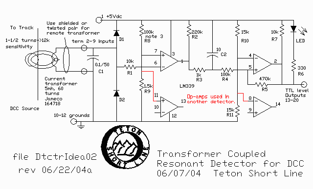
Description: DETECTOR 2 was designed in the mid-1970s to be non-inductive and to respond to any current from DC up to any reasonable frequency desired in the future. Additional blocks were incorporated into the TSL, and an Automatic Cab Control (ACC) system was implemented. Experiments were conducted with over-the-track sound systems using AM carriers in the 200 kHz range, necessitating a design that avoided the inductance of older transformers. The new detector features a high output current capacity (1 amp sink) to drive existing 12-volt panel lamps and 5-volt logic for the ACC. As a general-purpose current detector, it has applications beyond model railroading. The circuit employs the established method of utilizing the constant voltage drop across a silicon diode for the sense signal. The signal polarity adjusts one of the inputs to the LM3900 Norton op-amp. At high frequencies, the slew rate limit of the op-amp results in continuous turn-on, minimizing concerns regarding upper frequency limits. However, with 20 kHz high-frequency lighting, it was necessary to desensitize some detectors with capacitors to mitigate undesired tripping caused by the capacitance of long feedlines. A regulated source for the Vcc supply is crucial, and the operating voltage (Vcc) and sensitivity can be easily adjusted by selecting appropriate resistor values (R1 and R2) in the input divider; higher impedance yields higher sensitivity. The arithmetic for this is straightforward—select R1 and R2 values that produce voltages e1 and e2 allowing for a 0.65-volt drop across diode CR3. This is a three-terminal current sensing device, meaning the input current shares a common ground with the output signal, leading to three terminals instead of four and no isolation. This design is suitable only for a "common rail" wired system where one rail of every block ultimately connects to a common ground. This is analogous to an automobile where the battery, alternator, and lights share a terminal connected to the metal chassis. The detector performed effectively with the new DCC system while maintaining common rail wiring. DCC operates at a nominal 8 kHz but includes various higher harmonics in its square wave. The circuit is not suitable for a balanced feed DCC system utilizing multiple power boosters. DETECTOR 3 is a revision of the earlier DETECTOR 1 from the 1960s, employing an isolation transformer sourced from surplus materials for a local module club that required a four-terminal device due to wiring standards prohibiting common rail. The transformer was originally a "tube-voice-coil" type with an impedance ratio of approximately 5000/3.2 ohms. The outer speaker coil winding was removed, and around eight turns of 18-gauge wire were rewound onto it. This design does not function with pure DC but operates effectively with power supply ripple, pulses, or any AC component, making it suitable for DCC applications. Contemporary transformers would likely be toroidal. Three of these devices remain operational on the TSL’s Termite Timber Line (TTL) branch, contributing to an automated train operation running a doodlebug between Malfunction Junction and the high mountain town of Moosemilk. The module club's usage was discontinued for unrelated reasons. DETECTOR 4 emerged from extensive discussions with key figures in the Digital Command Control (DCC) community, leading to the conclusion that the traditional common rail wiring concept should be abandoned in favor of balanced feed systems, referred to as "home wiring" by some. This system allows both rails to float, with the only connections to GROUND or COMMON established through the H-bridge of the DC booster. A significant advantage of this approach is that the only voltages present on any rail, relative to GROUND or COMMON, are either zero or +14 volts (typical for HO scale), ensuring that no combination of rails across gaps can exceed these limits.
The DETECTOR 2 circuit utilizes a silicon diode to sense current, taking advantage of its forward voltage drop for input to the LM3900 Norton op-amp. This op-amp configuration allows for precise detection of varying current levels, with the output capable of sinking up to 1 amp, suitable for driving panel lamps and logic circuits. The selection of resistors R1 and R2 in the input divider network is crucial for tailoring the sensitivity and operating voltage of the detector. By adjusting these resistor values, the voltage drop across CR3 can be maintained at the desired level, ensuring reliable operation across a range of input currents. The design's non-inductive nature is particularly beneficial for applications involving high-frequency signals, where traditional transformers may introduce unwanted inductance.
The DETECTOR 3 variant enhances functionality by incorporating an isolation transformer, enabling operation in environments where common rail wiring is not permitted. The transformer design allows for effective detection of AC components, making it suitable for DCC systems that may exhibit ripple or pulsed signals. The adaptation of an existing transformer for use in this application demonstrates resourcefulness and innovation in circuit design.
Finally, DETECTOR 4 represents a paradigm shift in wiring philosophy for DCC systems. By adopting a balanced feed approach, this design mitigates issues associated with common rail wiring, such as voltage discrepancies across gaps. The implementation of floating rails simplifies the electrical architecture and enhances the reliability of the DCC system, ensuring consistent performance in model railroading applications. The advancements represented by these detector designs reflect ongoing innovations in the field, addressing both historical challenges and contemporary demands for performance and reliability in electronic circuits.DETECTOR 2 was designed back in the mid `70s to be non-inductive, and to respond to any current from DC up to any reasonable frequency that we might want in the future. I had added more blocks to the TSL and implemented our Automatic Cab Control (ACC) system. I was also experimenting with over-the-track sound systems using AM carriers in the 200 k Hz range and didn`t want the inductance of the old transformers. The new detector had high output current (1 amp sink) capacity to drive the existing 12 volt panel lamps as well as the 5 volt logic for the ACC. As a general purpose current detector, it has many uses outside of model railroading. Examining the circuit, you`ll find we used the old trick of a taking the constant voltage drop across a silicon diode for the sense signal.
The signal polarity raises or lowers one of the inputs to the LM3900 Norton op-amp. If the frequency is high the slew rate limit of the op-amp simply results in continuous turn-on, hence we are not much concerned with upper frequency limits, although with my 20kHz high frequency lighting, it was necessary to desensitize some detectors with capacitors, where the capacitance of long feedlines resulted in undesired tripping. A regulated source for the Vcc supply is essential. The operating voltage Vcc, and sensitivity is easily tailored by the selection of the resistor values R1 & R2 in the input divider i.
e. high impedance=high sensitivity. The arithmetic is simple- select values of R1 & R2 that will give you voltages e1 and e2 allowing about 0. 65 volt drop across diode CR3. This is a three terminal current sensing device. The three terminal part means that the input current goes to the same common ground as the output signal, hence three terminals instead of four and no isolation.
This is usable only in a "common rail" wired system where one rail of every block eventually reachs a "common" or "ground". Its like your automobile, where the battery, alternator and lights have one terminal tied to the metal chassis.
The detector worked great with my new DCC system while I retained the common rail wiring. DCC works at a nominal 8kHz, but contains many higher harmonics in its square wave. The circuit will NOT be appropriate for a balanced feed DCC system using more than one power booster. DETECTOR 3 is a re-work of the old `60`s DETECTOR 1 using an isolation transformer. We dug these out of the junk box for the local module club that needed a four terminal device, because the wiring standards do not permit common rail.
That old transformer was a "tube-voice-coil" product with an impedance ratio of about 5000/3. 2 ohms. That really doesn`t matter as we stripped off the outer speaker coil winding and wound about 8 turns of 18 guage wire back on it. This will not work with pure DC but if there is power supply ripple or pulse or any other AC component, then it works fine.
Should be great with DCC. Your transformer today would probably be a toroid. We still have three of these in service on the TSL`s Termite Timber Line (TTL) branch where they are part of an automated train operation running a doodlebug between Malfunction Junction and the high mountain town of Moosemilk. We`re trying hard to serve those folks in this time of rising costs. The module club use was discontinued for unrelated reasons. The Pix below shows a quad package. DETECTOR 4: I became convinced, after an extensive discertation with the movers and shakers of the Digital Command Control (DCC) world, that we need to give up the grandfatherly COMMON rail wiring concept and embrace the merits of balanced feed, called "home wiring" by some.
This system floats both rails, and they only find GROUND or COMMON back through the H-bridge of the DC booster. A major advantage is that the only possible voltages on any rail, relative to GROUND or COMMON, is ZERO or +14 Volts (typical for HO), and so no combination of rails across gaps can ever excee
The DETECTOR 2 circuit utilizes a silicon diode to sense current, taking advantage of its forward voltage drop for input to the LM3900 Norton op-amp. This op-amp configuration allows for precise detection of varying current levels, with the output capable of sinking up to 1 amp, suitable for driving panel lamps and logic circuits. The selection of resistors R1 and R2 in the input divider network is crucial for tailoring the sensitivity and operating voltage of the detector. By adjusting these resistor values, the voltage drop across CR3 can be maintained at the desired level, ensuring reliable operation across a range of input currents. The design's non-inductive nature is particularly beneficial for applications involving high-frequency signals, where traditional transformers may introduce unwanted inductance.
The DETECTOR 3 variant enhances functionality by incorporating an isolation transformer, enabling operation in environments where common rail wiring is not permitted. The transformer design allows for effective detection of AC components, making it suitable for DCC systems that may exhibit ripple or pulsed signals. The adaptation of an existing transformer for use in this application demonstrates resourcefulness and innovation in circuit design.
Finally, DETECTOR 4 represents a paradigm shift in wiring philosophy for DCC systems. By adopting a balanced feed approach, this design mitigates issues associated with common rail wiring, such as voltage discrepancies across gaps. The implementation of floating rails simplifies the electrical architecture and enhances the reliability of the DCC system, ensuring consistent performance in model railroading applications. The advancements represented by these detector designs reflect ongoing innovations in the field, addressing both historical challenges and contemporary demands for performance and reliability in electronic circuits.DETECTOR 2 was designed back in the mid `70s to be non-inductive, and to respond to any current from DC up to any reasonable frequency that we might want in the future. I had added more blocks to the TSL and implemented our Automatic Cab Control (ACC) system. I was also experimenting with over-the-track sound systems using AM carriers in the 200 k Hz range and didn`t want the inductance of the old transformers. The new detector had high output current (1 amp sink) capacity to drive the existing 12 volt panel lamps as well as the 5 volt logic for the ACC. As a general purpose current detector, it has many uses outside of model railroading. Examining the circuit, you`ll find we used the old trick of a taking the constant voltage drop across a silicon diode for the sense signal.
The signal polarity raises or lowers one of the inputs to the LM3900 Norton op-amp. If the frequency is high the slew rate limit of the op-amp simply results in continuous turn-on, hence we are not much concerned with upper frequency limits, although with my 20kHz high frequency lighting, it was necessary to desensitize some detectors with capacitors, where the capacitance of long feedlines resulted in undesired tripping. A regulated source for the Vcc supply is essential. The operating voltage Vcc, and sensitivity is easily tailored by the selection of the resistor values R1 & R2 in the input divider i.
e. high impedance=high sensitivity. The arithmetic is simple- select values of R1 & R2 that will give you voltages e1 and e2 allowing about 0. 65 volt drop across diode CR3. This is a three terminal current sensing device. The three terminal part means that the input current goes to the same common ground as the output signal, hence three terminals instead of four and no isolation.
This is usable only in a "common rail" wired system where one rail of every block eventually reachs a "common" or "ground". Its like your automobile, where the battery, alternator and lights have one terminal tied to the metal chassis.
The detector worked great with my new DCC system while I retained the common rail wiring. DCC works at a nominal 8kHz, but contains many higher harmonics in its square wave. The circuit will NOT be appropriate for a balanced feed DCC system using more than one power booster. DETECTOR 3 is a re-work of the old `60`s DETECTOR 1 using an isolation transformer. We dug these out of the junk box for the local module club that needed a four terminal device, because the wiring standards do not permit common rail.
That old transformer was a "tube-voice-coil" product with an impedance ratio of about 5000/3. 2 ohms. That really doesn`t matter as we stripped off the outer speaker coil winding and wound about 8 turns of 18 guage wire back on it. This will not work with pure DC but if there is power supply ripple or pulse or any other AC component, then it works fine.
Should be great with DCC. Your transformer today would probably be a toroid. We still have three of these in service on the TSL`s Termite Timber Line (TTL) branch where they are part of an automated train operation running a doodlebug between Malfunction Junction and the high mountain town of Moosemilk. We`re trying hard to serve those folks in this time of rising costs. The module club use was discontinued for unrelated reasons. The Pix below shows a quad package. DETECTOR 4: I became convinced, after an extensive discertation with the movers and shakers of the Digital Command Control (DCC) world, that we need to give up the grandfatherly COMMON rail wiring concept and embrace the merits of balanced feed, called "home wiring" by some.
This system floats both rails, and they only find GROUND or COMMON back through the H-bridge of the DC booster. A major advantage is that the only possible voltages on any rail, relative to GROUND or COMMON, is ZERO or +14 Volts (typical for HO), and so no combination of rails across gaps can ever excee

Low-power-magnetic-current-sensor
A transducer senses direct current magnetically, providing isolation between the input and the output. The detecting and isolating element is a saturable reactor, through which the input current to be measured passes via a one-turn control coil. The transducer offers...

DC arc welding machine no-load power path from 2
The DC arc welding machine is connected to the secondary load path of the power circuit as illustrated in the figure. This circuit is designed for use during extended downtime, approximately lasting a few minutes, and is not suitable for...

High-Gain Current Sensor
A high-gain amplifier utilizing a UA741 is employed to sense the relative voltage drop across a conductor, thereby measuring the current flowing through it. The sensitivity can be enhanced by increasing i2 to 10. LED1 and LED2 serve as indicators...

Current Sensor Board
The Current Sensor Board features an Atmel AVR AT90S8535 microcontroller operating at 8 MHz. It samples six ADC current inputs and utilizes the remaining two ADC inputs for controlling an integrating charge counter. The processed results are encapsulated into data...

DC shunt regulator power supply circuit
A DC shunt regulator power supply circuit is presented, which operates in parallel with a radio circuit. The circuit begins with an AC voltage of 22V, which is stepped down to 8V using a transformer. The 8V AC voltage is...

Robot Tutorials current sensor
Current sensing involves detecting the amount of current being used by a specific circuit or device. It is particularly useful for assessing the power consumption of various components within a robotic system. Although not commonly required in robotics, current sensing...

Current Sensor Testing and calibration
Connect the negative side of the positive supply to the positive side of the negative supply to create a ±15 VDC. This junction serves as the ground for the transducer, ensuring a balanced voltage. Continue the experiment by switching off...
DC shunt regulator power supply circuit
A DC shunt regulator power supply circuit is presented, which operates in parallel with a radio circuit. The circuit begins with an AC voltage of 22V, which is stepped down to 8V using a transformer. The 8V AC voltage is...