


Opto switches consist of a transmitter and receiver
#opto switch
#transmitter
#receiver
#mechanical arm
#magnet
#playfield
#game mechanism
#ball release
#sensor circuit
#mechanical sensor

Description: The game was originally designed to position three balls locked in holes on a slowly rotating ring around the Deadworld. Once the third ball was secured, a mechanical arm would release them, dropping the balls onto the playfield. This mechanism was part of the original software ROM. However, issues arose if the arm or the magnet it contained malfunctioned. Consequently, the software was modified so that the third ball was the only one locked on the ring, while the first two would pass the ring entrance and become "virtual" locks. Additionally, the ring's design was altered to feature slots instead of holes, allowing any ball that inadvertently landed on the ring to fall off as it rotated. In a home setting, the likelihood of arm failure is reduced, prompting the idea to restore the original functionality of the ball lock. Previous inquiries in the rec.games.pinball newsgroup about restoring the Deadworld yielded no results until October of last year, when the Shoot 'M Again team uploaded the ROM to the Internet Pinball Database. Initially, the prototype Judge Dredd included an opto switch near the entrance to the left ramp (switch 32), which was later relocated up the ramp and renumbered to switch 67. The next step involved converting switch 67 back to 32, as switch 67 was not utilized in the production L_1 ROM. Opto switches consist of a transmitter and receiver and require a separate opto board for the Judge Dredd pinball machine. To facilitate the switch number change, a spare opto switch (65) was repurposed. In this modification, switch 65 was assigned to column 3, while switch 67 was linked to row 2 to effectively convert it to switch 32. The subsequent task involved creating a new locking ring with holes instead of slots, accomplished using a router and a circle-cutting jig, followed by drilling holes with a 22mm flat cutting bit. Finally, the provided wire must be inserted into the multiplug corresponding to J3 pin 9, which can be performed using a small flat-head screwdriver or an IDC insertion tool.
The original design of the pinball game incorporated a mechanical ball lock system that relied on a rotating ring mechanism. This system was intended to enhance gameplay by allowing players to strategically lock balls in place before they were released onto the playfield. The mechanical arm's failure posed challenges, necessitating a software update to maintain game functionality. The transition from physical locks to virtual locks for the first two balls demonstrated an adaptive approach to circumvent mechanical issues while preserving gameplay dynamics.
The modification process outlined not only restores the original functionality but also enhances the reliability of the system in a home environment. The use of opto switches illustrates a modern approach to detecting ball positions without the wear and tear associated with mechanical switches. The conversion of switch numbers and the creation of a new locking ring highlight the ingenuity involved in retrofitting older pinball machines with updated components.
In terms of construction, the routing and drilling processes require precision to ensure that the new locking ring functions correctly. The use of a circle-cutting jig and a flat cutting bit ensures uniformity in the holes, which is critical for the locking mechanism's performance. Proper insertion of the wire into the multiplug is essential for maintaining electrical connections and ensuring that the opto switches operate as intended.
Overall, this detailed modification process exemplifies the intersection of electronics and mechanical design in the realm of pinball machine restoration, emphasizing the importance of adaptability and innovation in maintaining and enhancing classic gaming experiences.The game as originally envisaged placed the three balls as they were locked in holes on a slowly rotating ring around the Deadworld. When the third ball was locked, they were released by a mechanical arm and dropped onto the playfield.
This was how it worked in the original software ROM. The problem arose if the arm - or the magnet it contained - failed to work. This would mean there was no way to release the balls, so the software was changed to only lock the third ball on the ring - the first two sailed past the ring entrance and became "virtual" locks instead. In addition, the ring was changed so the holes became slots. That way, if a ball erroneously ends up on the ring, as it turns, the ball will simply fall off. In a home environment though, the potential for the arm to fail is minimised so wouldn`t it be nice to restore the functionality and make the ball lock work as originally intended I had previously looked on the rec.
games. pinball newsgroup to see if anyone had been able to restore the Deadworld, but no one could find the original ROM. Then in October of last year I saw that The Shoot `M Again team ” had uploaded the Rom to the Internet Pinball Database.
Originally the prototype Judge Dredd had an opto switch near the entrance to the left ramp (switch 32), later this switch was moved up the ramp and changed number to switch 67. The next step was to try to convert switch 67 back to 32 (switch 67 was not used on the production L_1 rom).
Opto switches consist of a transmitter and receiver and need a separate opto board on the Judge Dredd pinball. In order to make the switch number change I needed to use a spare opto switch (65). In the modification switch 65 became column 3 and 67 was linked to row 2 to make 67 become 32. The next task was to make the new locking ring with holes instead of slots. I did this using a router and a circle cutting jig. This produced the ring, then the holes were drilled using a 22mm flat cutting bit. - Next take the provided wire and insert it in to the multiplug corresponding to J3 pin 9. This can be done using a small flat head screw driver or an IDC insertion tool.
The original design of the pinball game incorporated a mechanical ball lock system that relied on a rotating ring mechanism. This system was intended to enhance gameplay by allowing players to strategically lock balls in place before they were released onto the playfield. The mechanical arm's failure posed challenges, necessitating a software update to maintain game functionality. The transition from physical locks to virtual locks for the first two balls demonstrated an adaptive approach to circumvent mechanical issues while preserving gameplay dynamics.
The modification process outlined not only restores the original functionality but also enhances the reliability of the system in a home environment. The use of opto switches illustrates a modern approach to detecting ball positions without the wear and tear associated with mechanical switches. The conversion of switch numbers and the creation of a new locking ring highlight the ingenuity involved in retrofitting older pinball machines with updated components.
In terms of construction, the routing and drilling processes require precision to ensure that the new locking ring functions correctly. The use of a circle-cutting jig and a flat cutting bit ensures uniformity in the holes, which is critical for the locking mechanism's performance. Proper insertion of the wire into the multiplug is essential for maintaining electrical connections and ensuring that the opto switches operate as intended.
Overall, this detailed modification process exemplifies the intersection of electronics and mechanical design in the realm of pinball machine restoration, emphasizing the importance of adaptability and innovation in maintaining and enhancing classic gaming experiences.The game as originally envisaged placed the three balls as they were locked in holes on a slowly rotating ring around the Deadworld. When the third ball was locked, they were released by a mechanical arm and dropped onto the playfield.
This was how it worked in the original software ROM. The problem arose if the arm - or the magnet it contained - failed to work. This would mean there was no way to release the balls, so the software was changed to only lock the third ball on the ring - the first two sailed past the ring entrance and became "virtual" locks instead. In addition, the ring was changed so the holes became slots. That way, if a ball erroneously ends up on the ring, as it turns, the ball will simply fall off. In a home environment though, the potential for the arm to fail is minimised so wouldn`t it be nice to restore the functionality and make the ball lock work as originally intended I had previously looked on the rec.
games. pinball newsgroup to see if anyone had been able to restore the Deadworld, but no one could find the original ROM. Then in October of last year I saw that The Shoot `M Again team ” had uploaded the Rom to the Internet Pinball Database.
Originally the prototype Judge Dredd had an opto switch near the entrance to the left ramp (switch 32), later this switch was moved up the ramp and changed number to switch 67. The next step was to try to convert switch 67 back to 32 (switch 67 was not used on the production L_1 rom).
Opto switches consist of a transmitter and receiver and need a separate opto board on the Judge Dredd pinball. In order to make the switch number change I needed to use a spare opto switch (65). In the modification switch 65 became column 3 and 67 was linked to row 2 to make 67 become 32. The next task was to make the new locking ring with holes instead of slots. I did this using a router and a circle cutting jig. This produced the ring, then the holes were drilled using a 22mm flat cutting bit. - Next take the provided wire and insert it in to the multiplug corresponding to J3 pin 9. This can be done using a small flat head screw driver or an IDC insertion tool.

Test Transmitter
The Test Transmitter (A3020) is a combination of three circuits designed to test the Subcutaneous Transmitter (A3019) and to analyze surface acoustic wave (SAW) voltage-controlled oscillators (VCOs). The A3020 incorporates the complete A3019 circuit in its central section, which closely...
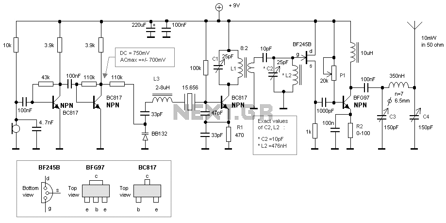
50MHz crystal bug
This bugg is based on my previous 3-transistor transmitter. This bugg unit has many advantages. The transmitter uses a crystal 46.515MHz to hold a steady frequency. The frequency can be fine-tuned by some 100kHz. The transmitter can send data and...

LW, MW and SW bands Receiver
This is a compact three transistor regenerative general coverage receiver with fixed feedback. It's based on the principle of the ZN414 only much higher coverage. The sensitivity and selectivity is relatively good (especially on the LF and MW bands) as...

80M And 40M Cw-Ssb Receiver Circuit
This direct-conversion receiver utilizes a TDA7000 integrated circuit (IC) and incorporates an LM386 audio amplifier. The TDA7000 serves as the mixer and local oscillator (L.O.) section. The frequency control can be achieved using either an air variable capacitor or a...

transmitter circuit diagram
Clearly indicate on the circuit diagram each type and size of the components. There is a need for assistance in designing a low power FM transmitter circuit, specifically using the BA1404 FM transmitter with a center frequency of 79W and...
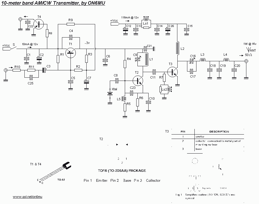
1watt AM/CW 10-meter band transmitter
In this project, you will make a simple 3-stage low-power broadcast-type circuit, using a crystal oscillator integrated circuit and a collector modulated AM oscillator with amplifier. You can connect the circuit to an electret microphone or amplified dynamic microphone. Using...

A Simple 80M Direct Conversion Receiver
A few weeks ago, Jason NT7S mentioned the ZL2BMI DSB transceiver as a rig that might be of interest for building. He was correct; it had been seen in SPRAT, but for some reason, it had not been seriously considered...
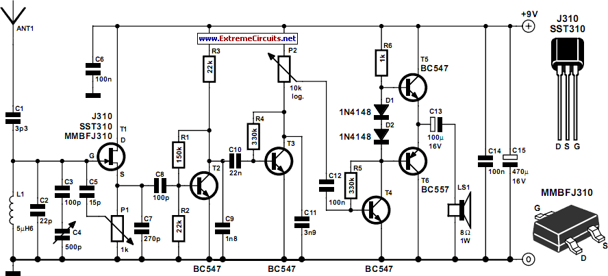
Tuned Radio Frequency (TRF) Receiver
Superheterodyne receivers have been mass-produced since around 1924, but for reasons of cost did not become successful until the 1930s.
Superheterodyne receivers represent a pivotal advancement in radio technology, characterized by their ability to convert high-frequency signals into lower intermediate...

Original 2N2/40 Schematic Diagrams
This section describes the components of the receiver, which includes the post-mixer amplifier, variable crystal filter, intermediate frequency (IF) amplifier, product detector, local oscillator, receiver muting, and audio amplifier. The transmit section features the local oscillator, transmit single balanced mixer,...