


Paper-sheet-discriminator
#opto-detector
#Schmitt trigger
#motor control
#noise immunity
#paper discrimination
#Darlington
#transistor
#SC148D
#H23B

Description: The circuit provides power to the drive motor when one or no sheets are fed, but interrupts motor power when two or more overlapping sheets pass through the optodetector slot. The optodetector can be either an H2aB Darlington interruptor module or an H23B matched emitter-detector pair. The output from the optodarlington is connected to a Schmitt trigger, which includes transistors Q1 and Q2 for noise immunity and to accommodate minor variations in paper opacity. When the Schmitt trigger is activated, gate current is supplied to the SC148D output device. The power supply for the detector and Schmitt trigger is a simple RC diode half-wave configuration, selected for its low cost (fewer diodes and no transformers) and minimal bulk. Although this supply is directly coupled to the power triac, this is limited by current drain considerations (50 mA DC for the gate drive alone). It should be noted that direct coupling of the Schmitt trigger to the output triacs is preferred, as RFI is virtually eliminated with the quasi-DC gate drive.
The described circuit is designed to control a drive motor based on the presence of sheets in a feeding mechanism. The primary function of the circuit is to ensure that the motor operates only when the appropriate number of sheets is detected, thereby preventing jams or misfeeds that could occur if multiple sheets are fed simultaneously.
The optodetector plays a crucial role in this mechanism. It detects the number of sheets passing through its slot and provides feedback to the control circuitry. The choice of either the H2aB Darlington interruptor module or the H23B matched emitter-detector pair allows for flexibility in component selection based on availability and specific application requirements.
The Schmitt trigger configuration, utilizing transistors Q1 and Q2, enhances the reliability of the signal by providing noise immunity. This is particularly important in environments where electrical noise may affect the performance of the circuit. The Schmitt trigger also compensates for variations in paper opacity, ensuring consistent operation regardless of the type of sheets being fed.
The output of the Schmitt trigger is connected to the SC148D output device, which is responsible for driving the motor. The use of a simple RC diode half-wave power supply for the detector and Schmitt trigger is a cost-effective solution that minimizes component count and space requirements. However, care must be taken regarding the current drain, as the gate drive for the triac requires a significant amount of current (50 mA DC).
To ensure optimal performance and reduce the risk of radio frequency interference (RFI), direct coupling of the Schmitt trigger to the output triacs is implemented. This design choice enhances the overall reliability of the circuit and ensures that the motor operates smoothly without unintended interruptions or noise issues.The circuit outputs power to the drive motor when one or no sheets are being fed, but interrupts motor power when two or more superimposed sheets pass through the optodetector slot. The optodetector can be either an H2aB darlington interruptor module or an H23B matched emitter -detector pair.
The output from the optodarlington is coupled to a Schmitt trigger, comprising transistors Ql and Q2 for noise immunity and minor paper opacity variation immunity. When the Schmitt is on, gate current is applied to the SC148D output device. The de power supply for the detector and Schmitt is a simple rc diode halfwave configuration chosen for its low cost (fewer diodes and no transformers) and minimum bulk. While such a supply is directly coupled to the power triac, this is precluded by current drain considerations (50 mA de for the gate drive alone).
Note that direct coupling of the Schmitt to the output triacs is preferred, since RFI is virtually eliminated with the quasi-de gate drive.
The described circuit is designed to control a drive motor based on the presence of sheets in a feeding mechanism. The primary function of the circuit is to ensure that the motor operates only when the appropriate number of sheets is detected, thereby preventing jams or misfeeds that could occur if multiple sheets are fed simultaneously.
The optodetector plays a crucial role in this mechanism. It detects the number of sheets passing through its slot and provides feedback to the control circuitry. The choice of either the H2aB Darlington interruptor module or the H23B matched emitter-detector pair allows for flexibility in component selection based on availability and specific application requirements.
The Schmitt trigger configuration, utilizing transistors Q1 and Q2, enhances the reliability of the signal by providing noise immunity. This is particularly important in environments where electrical noise may affect the performance of the circuit. The Schmitt trigger also compensates for variations in paper opacity, ensuring consistent operation regardless of the type of sheets being fed.
The output of the Schmitt trigger is connected to the SC148D output device, which is responsible for driving the motor. The use of a simple RC diode half-wave power supply for the detector and Schmitt trigger is a cost-effective solution that minimizes component count and space requirements. However, care must be taken regarding the current drain, as the gate drive for the triac requires a significant amount of current (50 mA DC).
To ensure optimal performance and reduce the risk of radio frequency interference (RFI), direct coupling of the Schmitt trigger to the output triacs is implemented. This design choice enhances the overall reliability of the circuit and ensures that the motor operates smoothly without unintended interruptions or noise issues.The circuit outputs power to the drive motor when one or no sheets are being fed, but interrupts motor power when two or more superimposed sheets pass through the optodetector slot. The optodetector can be either an H2aB darlington interruptor module or an H23B matched emitter -detector pair.
The output from the optodarlington is coupled to a Schmitt trigger, comprising transistors Ql and Q2 for noise immunity and minor paper opacity variation immunity. When the Schmitt is on, gate current is applied to the SC148D output device. The de power supply for the detector and Schmitt is a simple rc diode halfwave configuration chosen for its low cost (fewer diodes and no transformers) and minimum bulk. While such a supply is directly coupled to the power triac, this is precluded by current drain considerations (50 mA de for the gate drive alone).
Note that direct coupling of the Schmitt to the output triacs is preferred, since RFI is virtually eliminated with the quasi-de gate drive.

Wilf Rigter`s SIMD1 V2
In the never-ending quest for simplicity, even one extra diode is a price I loathe to pay. To avoid using extra components, it struck me that the two diodes in SIMD1 V1 were connected like the two junctions in one...

Speech compression circuit diagram
An amplifier designed to achieve a voltage gain of approximately 20, utilizing the MPS6517 PNP transistor in the emitter follower configuration. The RI controller allows for adjustment of the transistor's quiescent point. The output signal is activated only when the...
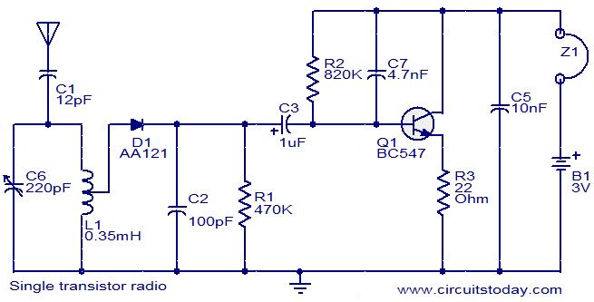
BC547 Single Transistor Radio
The circuit diagram of a simple radio that uses one transistor and a few other passive components. Component: Diode, Capacitor, Inductor, Resistor.
The circuit design for a simple radio receiver typically incorporates a single transistor as the active amplification element, along...

Transistor Hartley Oscillator
Any vacuum-tube oscillator configuration has an equivalent transistor circuit. For example, consider the vacuum-tube oscillator, illustrated in Fig. 6-1 (A), which represents one form of Hartley oscillator. Positive feedback is accomplished by arranging the resonant tank E to be common...
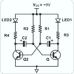
Astable Multivibrator with 2 Transistors
This circuit is straightforward and easy to construct, utilizing two transistors as active components along with several passive components such as resistors, capacitors, and two LEDs. The circuit employs the MPS2222 transistor, though any NPN type transistor can be used...

The SC (Schmitt Comparator) Head
I'll eventually post an explanation, but in the meantime, here it is. Meanwhile, a slightly refined version (with flashing LEDs to indicate "lock") was posted a few weeks later:
The provided description indicates a project involving a circuit that utilizes flashing...

One transistor audio mixer (2N3563)
This circuit mixer features internal amplification using a 2N3563 transistor. Two input signals can be independently adjusted via VRI and VR2. The VR3 balance control allows for the attenuation of one signal while the other remains active. Additionally, the transistor...

Tickler oscillator circuit
When the circuit is initially powered, neither transistor is activated, resulting in high base voltages for both and a tendency to turn on. Due to slight asymmetries, one transistor will activate first, leading the circuit into one of its states...

Electronic Horn
Electronic horn circuit diagram. When the power line is switched on, a basic tone is produced by transistor T2 and transformer X1, which is frequency-modulated by a wandering voltage generator affected by a low-frequency square wave generator. This is a...