


Phase reversal detector
#phase reversal
#phase sequence
#neon lamp
#voltage detector
#three-phase
#motor control
#safety circuit
#AC voltage
#indicator

Description: Assume the correct phase sequence to be VA-VB-VC. The circuit terminals are connected such that T1 gets connected to phase A and T2 to phase B. The capacitor advances the voltage developed across R2 due to phase B by 60°, while the voltage developed across it by phase A is in phase with VA. The net voltage developed across R2 is approximately zero, causing the neon lamp to remain unlit, which indicates the correct phase sequence. If terminal T2 is connected to phase C, a significant voltage, K(VA + VC 60°), develops across R2, energizing the neon indicator to signal a reverse phase sequence. The motor terminals can be connected to the three phases in six different combinations.
A three-phase motor will run in the forward direction for three of these combinations, while for the remaining three, it will operate in the reverse direction. The circuit is capable of detecting all three reverse combinations. This circuit can be integrated into any existing motor starter, allowing the operator to verify whether the phase sequence has been altered before starting the machine.
The described circuit utilizes a phase sequence detection mechanism that is critical in three-phase motor applications. The arrangement ensures that the motor operates correctly based on the established phase sequence of VA-VB-VC. The connection of T1 to phase A and T2 to phase B is essential for the proper functioning of the circuit. The capacitor plays a pivotal role by advancing the voltage from phase B by 60 degrees, which is necessary for the comparison with the voltage from phase A.
The voltages across R2 are monitored to determine the phase relationship. When the voltages are in phase, the resultant voltage across R2 approaches zero, which keeps the neon lamp off, indicating that the phase sequence is correct. Conversely, if T2 is mistakenly connected to phase C, the resulting voltage across R2 will increase significantly, leading to the activation of the neon lamp. This serves as a visual alert that the phase sequence is reversed, which could potentially damage the motor if it were to be operated under these conditions.
The circuit's design allows for six different configurations of motor terminal connections to the three-phase supply. Out of these, three configurations will allow the motor to run in the forward direction, while the remaining three will cause it to run in reverse. The ability to detect all three reverse combinations ensures that operators are informed of any incorrect phase connection before initiating motor operation, thereby enhancing operational safety and preventing equipment damage. This circuit can be effectively integrated into existing motor starters, enhancing their functionality and providing a straightforward means of phase sequence verification.Assume the correct phase sequence to be VA-VB-VC. The circuit terminals are connected such that Tl gets connected to phase A and T2 to phase B. The capacitor advances the voltage developed across R2 due to phase "B" by — 60°, while the voltages developed across it by phase "A" is in phase with VA as shown in Fig. 69-1. The net voltage developed across R2 ~ zero, the neon lamp is not energized, thereby signaling correct phase sequence.
If terminal T2 gets connected to phase C, a large voltage, K(VA + Vc 60°), gets developed across R2, energizing the neon indicator to signal reverse phase sequence. The motor terminals can be connected to the three phases in six different combinations. A three-phase motor will run in the forward direction for three such combinations, while for the other three it will operate in the reverse direction. As shown in the table, the circuit detects all three reverse combinations. This circuit can be wired into any existing motor starter where the operator can see whether the phase sequence has been altered, before starting the machine.
A three-phase motor will run in the forward direction for three of these combinations, while for the remaining three, it will operate in the reverse direction. The circuit is capable of detecting all three reverse combinations. This circuit can be integrated into any existing motor starter, allowing the operator to verify whether the phase sequence has been altered before starting the machine.
The described circuit utilizes a phase sequence detection mechanism that is critical in three-phase motor applications. The arrangement ensures that the motor operates correctly based on the established phase sequence of VA-VB-VC. The connection of T1 to phase A and T2 to phase B is essential for the proper functioning of the circuit. The capacitor plays a pivotal role by advancing the voltage from phase B by 60 degrees, which is necessary for the comparison with the voltage from phase A.
The voltages across R2 are monitored to determine the phase relationship. When the voltages are in phase, the resultant voltage across R2 approaches zero, which keeps the neon lamp off, indicating that the phase sequence is correct. Conversely, if T2 is mistakenly connected to phase C, the resulting voltage across R2 will increase significantly, leading to the activation of the neon lamp. This serves as a visual alert that the phase sequence is reversed, which could potentially damage the motor if it were to be operated under these conditions.
The circuit's design allows for six different configurations of motor terminal connections to the three-phase supply. Out of these, three configurations will allow the motor to run in the forward direction, while the remaining three will cause it to run in reverse. The ability to detect all three reverse combinations ensures that operators are informed of any incorrect phase connection before initiating motor operation, thereby enhancing operational safety and preventing equipment damage. This circuit can be effectively integrated into existing motor starters, enhancing their functionality and providing a straightforward means of phase sequence verification.Assume the correct phase sequence to be VA-VB-VC. The circuit terminals are connected such that Tl gets connected to phase A and T2 to phase B. The capacitor advances the voltage developed across R2 due to phase "B" by — 60°, while the voltages developed across it by phase "A" is in phase with VA as shown in Fig. 69-1. The net voltage developed across R2 ~ zero, the neon lamp is not energized, thereby signaling correct phase sequence.
If terminal T2 gets connected to phase C, a large voltage, K(VA + Vc 60°), gets developed across R2, energizing the neon indicator to signal reverse phase sequence. The motor terminals can be connected to the three phases in six different combinations. A three-phase motor will run in the forward direction for three such combinations, while for the other three it will operate in the reverse direction. As shown in the table, the circuit detects all three reverse combinations. This circuit can be wired into any existing motor starter where the operator can see whether the phase sequence has been altered, before starting the machine.
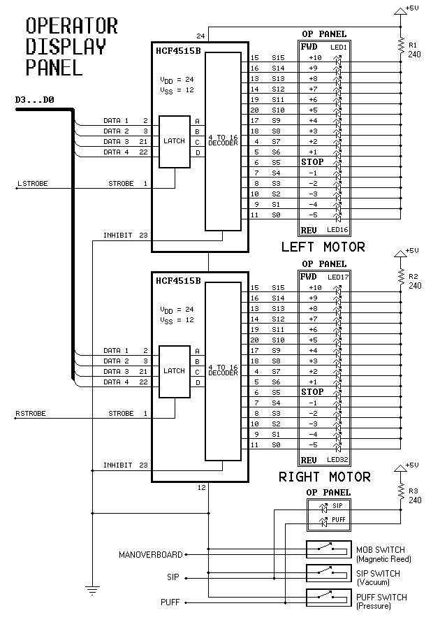
Dual-Motor SIP&PUFF Controlled Kayak System
The YouTube video below demonstrates the quick and easy setup of the system at the launch site.
The provided description indicates a focus on the efficiency of system installation at a launch site, as showcased in a YouTube video. In an...

Automatic AC voltage regulator circuit
Automatic AC voltage regulator circuit
The automatic AC voltage regulator circuit is designed to maintain a stable output voltage despite fluctuations in the input voltage. This circuit is essential for protecting sensitive electronic devices from voltage variations that can lead to...

Automatic AC voltage regulator circuit TXD1742 continuous adjustment
Automatic AC voltage regulator circuit TXD1742 with continuous adjustment.
The TXD1742 is an automatic AC voltage regulator circuit designed to provide continuous voltage adjustment, ensuring stable output voltage in varying load conditions. This circuit is particularly useful in applications where voltage...

Three-phase factor controller
The modified power-factor controller, developed at the Marshall Space Flight Center, utilizes a phase detector for each of the three phase windings of a delta-connected induction motor. The control mechanism is based on the sum of the phase differences.
Instabilities of...

Non-Contact AC Mains Voltage Detector
The circuit diagram of the non-contact voltage detector is illustrated in Figure 1. It consists of two main components: an AC amplifier and an audio oscillator, which is based on the Schmitt trigger DD1.1 of the IC CD4093, along with...

2 -Y- connection automatic three-speed motor acceleration control circuit
Figure 3-118 illustrates an automatic acceleration control circuit. This circuit employs a male contactor time relay, enabling the motor to start automatically at a low speed before transitioning to high-speed operation.
The automatic acceleration control circuit depicted in Figure 3-118 is...

A read-only phase sequence indicator circuit
The three-phase voltage waveform diagram illustrates that when one phase voltage transitions from positive to negative across the zero point, the subsequent phase voltage becomes positive while the third phase remains negative. The U terminal voltage is positive when steady...

Three phase torque motor speed control circuit
The circuit depicted in Figure 3-176 illustrates an adjustment method that allows the motor to operate at equilibrium. The adjustment range is relatively wide; however, it necessitates a three-phase voltage regulator, which incurs higher input costs.
The circuit design in Figure...

motor control inverter (AC drive) in mine industry
Motor control, energy efficiency of inverter (AC drive) selection, and parameters setting guidance in the mining industry: vector control, open loop or closed loop control, with energy braking unit or energy feedback unit.
In the context of motor control for the...