


Phase-sensitive rectifier circuit

Description: The transmitter (FZ) winding and receiver (SZ) correspond to the three-phase windings connected to a 110V AC voltage supply for transmission. The field winding, early start angle, and receiver output voltage at both ends of the stator windings reflect the angular displacement of the transmitter rotor. This displacement indicates both the magnitude and direction of the error angle between the transmitter and receiver. At equilibrium, the output voltage is zero; otherwise, an error occurs, resulting in a voltage signal output. The system includes a single-phase full-wave phase-sensitive rectifier, where two components operate alternately, providing a voltage output across a resistance of 5.1 kΩ. RP1 is used to adjust balance, converting the AC rectifier output into a DC signal, which is then sent through RP2 to the input of an operational amplifier (ST) for amplification.
The described circuit involves a three-phase winding system where the transmitter (FZ) and receiver (SZ) are integral components. The transmitter functions by generating a magnetic field, while the receiver measures the resultant output voltage across the stator windings. This configuration allows for the detection of angular displacement, which is critical for applications requiring precise positioning or speed control.
The system operates on a 110V AC supply, ensuring that the windings are energized adequately for optimal performance. The field winding is responsible for establishing the magnetic field necessary for the functioning of the transmitter. The early start angle is a crucial parameter that determines the initial position of the rotor, influencing the overall system response.
The output voltage at the stator windings is a direct reflection of the rotor's angular position. When the system is in equilibrium, the output voltage stabilizes at zero, indicating that the rotor is correctly positioned. However, any deviation from this position results in a voltage output that signifies an error angle. This feedback mechanism is vital for maintaining accurate control and ensuring the system operates within specified parameters.
The inclusion of a single-phase full-wave phase-sensitive rectifier is essential for converting the AC signal produced by the windings into a usable DC signal. This rectifier operates by allowing current to flow in one direction, effectively smoothing out the variations in the AC signal. The two rectifying components within the circuit work alternately, ensuring continuous output while maintaining the necessary voltage levels across the load.
The resistance of 5.1 kΩ serves to limit the current flowing through the circuit, providing a stable output voltage. The adjustment potentiometer RP1 is employed to fine-tune the balance of the circuit, ensuring that the output voltage remains within acceptable limits. Subsequently, the output from the rectifier is processed through another potentiometer, RP2, which controls the input to the operational amplifier (ST). This amplifier is responsible for further boosting the signal, enhancing the system's ability to detect and respond to changes in angular displacement accurately.
Overall, this circuit design exemplifies a sophisticated approach to measuring angular displacement in a three-phase system, incorporating feedback mechanisms and signal processing elements to achieve precise control and reliability in operation.Transmitter (FZ) winding and a receiver (sz) correspond to the three-phase windings connected, 110V AC voltage supplied to the transmission field winding, early start angle Qing, receiver output voltage at both ends of the stator windings and phase reflect the transmitter rotor angular displacement delivery that reflect the transmitter between the magnitude and direction of the error angle. At equilibrium, the output voltage is zero, otherwise, an error occurs, a voltage signal output. The picture shows the single-phase full-wave phase-sensitive rectifier. Two work alternately, respectively, in the resistance 5.lkfl voltage output, RP1 used to adjust the balance.
AC rectifier into a DC signal, the speed loop RP2 sent to the operational amplifier (ST) input amplification,
The described circuit involves a three-phase winding system where the transmitter (FZ) and receiver (SZ) are integral components. The transmitter functions by generating a magnetic field, while the receiver measures the resultant output voltage across the stator windings. This configuration allows for the detection of angular displacement, which is critical for applications requiring precise positioning or speed control.
The system operates on a 110V AC supply, ensuring that the windings are energized adequately for optimal performance. The field winding is responsible for establishing the magnetic field necessary for the functioning of the transmitter. The early start angle is a crucial parameter that determines the initial position of the rotor, influencing the overall system response.
The output voltage at the stator windings is a direct reflection of the rotor's angular position. When the system is in equilibrium, the output voltage stabilizes at zero, indicating that the rotor is correctly positioned. However, any deviation from this position results in a voltage output that signifies an error angle. This feedback mechanism is vital for maintaining accurate control and ensuring the system operates within specified parameters.
The inclusion of a single-phase full-wave phase-sensitive rectifier is essential for converting the AC signal produced by the windings into a usable DC signal. This rectifier operates by allowing current to flow in one direction, effectively smoothing out the variations in the AC signal. The two rectifying components within the circuit work alternately, ensuring continuous output while maintaining the necessary voltage levels across the load.
The resistance of 5.1 kΩ serves to limit the current flowing through the circuit, providing a stable output voltage. The adjustment potentiometer RP1 is employed to fine-tune the balance of the circuit, ensuring that the output voltage remains within acceptable limits. Subsequently, the output from the rectifier is processed through another potentiometer, RP2, which controls the input to the operational amplifier (ST). This amplifier is responsible for further boosting the signal, enhancing the system's ability to detect and respond to changes in angular displacement accurately.
Overall, this circuit design exemplifies a sophisticated approach to measuring angular displacement in a three-phase system, incorporating feedback mechanisms and signal processing elements to achieve precise control and reliability in operation.Transmitter (FZ) winding and a receiver (sz) correspond to the three-phase windings connected, 110V AC voltage supplied to the transmission field winding, early start angle Qing, receiver output voltage at both ends of the stator windings and phase reflect the transmitter rotor angular displacement delivery that reflect the transmitter between the magnitude and direction of the error angle. At equilibrium, the output voltage is zero, otherwise, an error occurs, a voltage signal output. The picture shows the single-phase full-wave phase-sensitive rectifier. Two work alternately, respectively, in the resistance 5.lkfl voltage output, RP1 used to adjust the balance.
AC rectifier into a DC signal, the speed loop RP2 sent to the operational amplifier (ST) input amplification,

Half-wave rectifier circuit principle
A bridge rectifier capacitor filter serves as a primary power supply for current amplifier circuits. This power supply configuration is straightforward and offers enhanced performance. The bridge rectifier circuit is a full-wave rectifying circuit, meaning it converts both the positive...
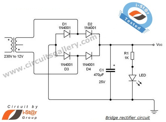
diode bridge rectifier circuits
A rectifier is an electronic circuit that converts AC voltage to DC voltage. It can be implemented using a combination of capacitors and diodes. The unique property of diodes, which allows current to flow in a single direction, is utilized...

Transmitter Negative Key Line Keyer
Using an NTE288 (or ECG288, GE223, or SK3434), this circuit can key a negative line up to -300 V maximum. Do not use this circuit to key a vacuum-tube amplifier that draws grid current because the keying transistor might be...

CF1 CF2 main circuit
AC voltage is rectified by a bridge (VD1-VD4). A resistor (R1) limits the buck, while diode (VD5) provides clipping. A trapezoidal wave is generated as the trigger circuit for DC voltage and synchronization. When the base of transistor (VT1) receives...

AC polarity detection
The circuit should be capable of detecting voltages between 230 VAC and 120 VAC to 250 VAC, making it suitable for both US and EU applications. A non-isolated circuit was found, but it fails to simulate correctly due to ground...

Half-wave rectifier
This circuit allows for precise half-wave rectification of the incoming signal. It exhibits a gain of 0 for positive signals and a gain of -1 for negative signals. By reversing the orientation of both diodes, the output polarity can be...

100W Medium Frequency Transmitter
The 100W4 is a two-tube medium frequency transmitter designed for pre-tuning to three frequencies within the medium frequency band, supporting emissions types A1, A2, and A3. In the A1 configuration, both tubes function as parallel oscillators. For A2 and A3...
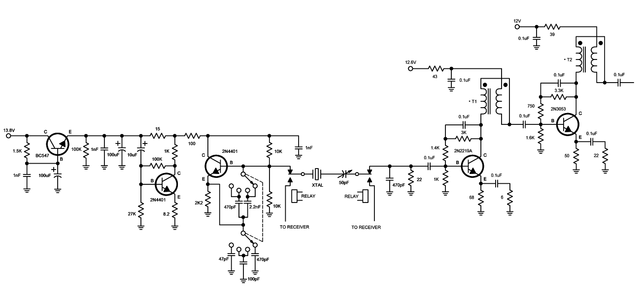
Deluxe Crystal Controlled Transmitter
A high-quality QRP transmitter, named NEXUS 6, is designed to explore issues related to extremely narrow bandwidth communication. This device is not merely a simplified version of a QRP transmitter; it aims to create a cost-effective system that can be...

Simple Valve MW Transmitter circuit 30W
The simplicity of this transmitter, combined with its high performance, makes it particularly interesting. It has an output power of approximately 30 W, and under normal conditions, with the appropriate antenna and handling, it can achieve a range of 30...