


Photo relay circuit
#photo relay
#light activated
#photo diode
#relay
#light sensor
#circuit
#reverse biased
#high resistance

Description: A photo relay, or light-activated relay, is a circuit that opens and closes relay contacts based on the presence of light. It utilizes a photodiode to detect light levels. The photodiode exhibits high resistance in the absence of light and is connected in reverse bias. The only current flowing through it is due to minority carriers. When light strikes the photodiode, the current from the minority carriers increases, resulting in lower resistance. Consequently, the voltage across the photodiode is insufficient to forward bias transistor Q1, keeping the relay in the OFF state. In darkness, the photodiode's resistance increases, and the voltage across it becomes adequate to forward bias transistor Q1, turning the relay ON. Diode D2 acts as a freewheeling diode, protecting the transistor from transients generated during relay switching. This configuration allows the load connected through the relay contacts to be switched ON and OFF based on the light incident on the photodiode.
The photo relay circuit operates through a straightforward mechanism that hinges on the properties of the photodiode and transistor. In the absence of light, the photodiode maintains a high resistance, which prevents significant current flow. This condition keeps the voltage across it at a level that does not suffice to forward bias the transistor Q1, thereby ensuring that the relay remains in the OFF state and the load remains disconnected.
Upon exposure to light, the photodiode's resistance drops as the minority carrier current increases. This change results in a lower voltage across the photodiode. If the voltage surpasses the threshold required to forward bias Q1, the transistor conducts, allowing current to flow through the relay coil. As a result, the relay contacts close, connecting the load to the power supply.
Moreover, the inclusion of diode D2 is crucial for protecting the transistor from voltage spikes that can occur when the relay coil is de-energized. These transients, generated by the collapsing magnetic field of the relay, can induce back electromotive force (EMF) that may damage the transistor. The freewheeling diode provides a path for this induced current, effectively clamping the voltage and safeguarding the transistor.
Overall, this circuit configuration exemplifies an effective method for controlling a load based on light intensity, leveraging the unique characteristics of photodiodes and transistors, while ensuring reliability through protective components.A photo relay or light activated relay is a circuit which opens and closes the relay contacts according to the light. Here a photo diode is used to sense the light. The photo diode offers a high resistance when there is no light falling on it. Here the photo diode is connected in reverse biased condition. The only current flowing through it will be du e to the minority carriers. When light falls on it, the current due to the minority carriers increase and the diode offers a low resistance. As a result the voltage across the diode will not be sufficient to make the transistor Q1 forward biased and the relay will OFF.
When there is darkness the photo diode resistance increases and the voltage across it will become enough to forward bias the transistor Q1 making the relay ON. The diode D2 is used as a freewheeling diode to protect the transistor from transients produced to the switching of relay.
By this way the load connected through the relay contacts can be switched ON and OFF according to the light falling on the photo diode.
The photo relay circuit operates through a straightforward mechanism that hinges on the properties of the photodiode and transistor. In the absence of light, the photodiode maintains a high resistance, which prevents significant current flow. This condition keeps the voltage across it at a level that does not suffice to forward bias the transistor Q1, thereby ensuring that the relay remains in the OFF state and the load remains disconnected.
Upon exposure to light, the photodiode's resistance drops as the minority carrier current increases. This change results in a lower voltage across the photodiode. If the voltage surpasses the threshold required to forward bias Q1, the transistor conducts, allowing current to flow through the relay coil. As a result, the relay contacts close, connecting the load to the power supply.
Moreover, the inclusion of diode D2 is crucial for protecting the transistor from voltage spikes that can occur when the relay coil is de-energized. These transients, generated by the collapsing magnetic field of the relay, can induce back electromotive force (EMF) that may damage the transistor. The freewheeling diode provides a path for this induced current, effectively clamping the voltage and safeguarding the transistor.
Overall, this circuit configuration exemplifies an effective method for controlling a load based on light intensity, leveraging the unique characteristics of photodiodes and transistors, while ensuring reliability through protective components.A photo relay or light activated relay is a circuit which opens and closes the relay contacts according to the light. Here a photo diode is used to sense the light. The photo diode offers a high resistance when there is no light falling on it. Here the photo diode is connected in reverse biased condition. The only current flowing through it will be du e to the minority carriers. When light falls on it, the current due to the minority carriers increase and the diode offers a low resistance. As a result the voltage across the diode will not be sufficient to make the transistor Q1 forward biased and the relay will OFF.
When there is darkness the photo diode resistance increases and the voltage across it will become enough to forward bias the transistor Q1 making the relay ON. The diode D2 is used as a freewheeling diode to protect the transistor from transients produced to the switching of relay.
By this way the load connected through the relay contacts can be switched ON and OFF according to the light falling on the photo diode.

R/C On/Off Motor Controller with Brake
A relay-based on/off controller on the other hand can be very efficient. A typical relay has a contact resistance of 3 milliOhm. At 20A, this translates to a voltage drop of 0.06 volts, with a power loss of 1.2W. The...

Light Sensor Circuit
An ambient light sensor circuit is a circuit that utilizes light intensity to perform various applications.
An ambient light sensor circuit typically consists of a light-dependent resistor (LDR) or phototransistor that detects the intensity of ambient light. The sensor converts the...

bypass which improves the ability to resist surging of relay contact
During the power-up of the apparatus, the capacitor is primarily responsible for the emergence of surge current. The schematic diagram of the principle is illustrated in Fig. 1. After K1 closes, the capacitor begins to charge, assuming that the direct...

Isolated 24V Relay Controller
This is a common control voltage in industrial and telecommunications equipment, making relays frequently found in surplus equipment. Many relays can operate effectively on both AC and DC, providing a straightforward solution when the control voltage is switched mechanically, such...

Digital Light Sensor
The Intersil ISL29001 is a digital light sensor designed to measure light intensity and easily interface with a microcontroller.
The Intersil ISL29001 is a highly integrated digital light sensor that operates using a photodiode and an analog-to-digital converter (ADC) to provide...

light sensor circuit
This is a sensor circuit designed for light detection. It utilizes the LM311 comparator and features a simple design. The comparator is powered by a 12 V DC supply and does not require a negative supply for efficient operation. Feedback...

switch with relay schematic
The Light Switch with Relay is a series of electronic switches that are controlled by light intensity. This circuit can automatically control lighting, turning the lights on when ambient light levels decrease. The threshold for light activation in the Light...

Light Controlled Relays
The first circuit energizes the relay when the light rises above the preset level. The second circuit energizes the relay when the light falls below the preset level. The two circuits are practically identical. The only difference between them is...
Relay Coil Energy Saver
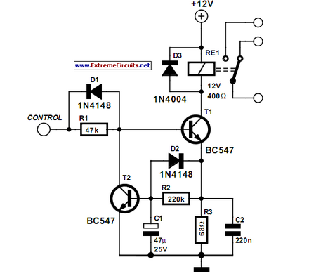
Some relays will become warm if they remain energized for some time. The circuit shown here will actuate the relay as before but then reduce the hold current.
The described circuit addresses the issue of heat generation in relays due to...