


Pine Racecar Victory Judge
#pinewood derby
#race judge
#LED indicator
#winner detection
#sensor
#simple circuit
#educational
#hobby

Description: I have received countless emails asking for a circuit to tell the user which car won in a pine car (also called Pinewood Derby, Cub Car, Scout Car, etc.) race. This simple circuit takes care of the guesswork, lighting the appropriate LED to indicate the winner. More: S1 and S2 are small lever type micro switches. Most any kind will do, as long as they are sensitive enough to be activated by the wheels of the cars. They should be positioned on the track so that the front wheels of the cars will run over them as the car.
The circuit designed to determine the winner of a Pinewood Derby race incorporates two micro switches (S1 and S2) that serve as the primary sensors to detect the cars' positions. Each switch is strategically placed along the racing track, ensuring that the front wheels of the cars activate the switches as they cross the finish line.
When a car crosses the first switch (S1), it completes a circuit that sends a signal to a microcontroller or a simple logic circuit, which can be designed using basic components such as resistors, capacitors, and diodes. The microcontroller processes the input and determines which switch was activated first, indicating the winner of the race.
Upon activation of S1, the circuit can light up a designated LED (LED1) that represents the first car to cross the finish line. If the second switch (S2) is activated before S1, the circuit will light up a different LED (LED2) to indicate that the second car has crossed the finish line first.
To enhance the functionality of the circuit, additional features such as a buzzer or sound module can be integrated to provide an auditory signal alongside the visual indication from the LEDs. This can further enhance the excitement of the race by announcing the winner audibly.
Powering the circuit can be achieved using a standard battery pack or a power supply, ensuring that the components operate reliably throughout the event. It is also advisable to include pull-down resistors on the micro switches to prevent false triggering when the switches are not engaged.
Overall, this circuit provides an efficient and straightforward solution for determining the winner of a Pinewood Derby race, utilizing basic electronic components to create an engaging and interactive experience for participants and spectators alike.I have received countless emails asking for a circuit to tell the user which car won in a pine car (also called Pinewood Derby, Cub Car, Scout Car, etc.) race. This simple circuit takes care of the guesswork, lighting the appropriate LED to indicate the winner.
S1 and S2 are small lever type micro switches. Most any kind will do, as long as they are sensitive enough to be activated by the wheels of the cars. They should be positioned on the track so that the front wheels of the cars will run over them as the car
The circuit designed to determine the winner of a Pinewood Derby race incorporates two micro switches (S1 and S2) that serve as the primary sensors to detect the cars' positions. Each switch is strategically placed along the racing track, ensuring that the front wheels of the cars activate the switches as they cross the finish line.
When a car crosses the first switch (S1), it completes a circuit that sends a signal to a microcontroller or a simple logic circuit, which can be designed using basic components such as resistors, capacitors, and diodes. The microcontroller processes the input and determines which switch was activated first, indicating the winner of the race.
Upon activation of S1, the circuit can light up a designated LED (LED1) that represents the first car to cross the finish line. If the second switch (S2) is activated before S1, the circuit will light up a different LED (LED2) to indicate that the second car has crossed the finish line first.
To enhance the functionality of the circuit, additional features such as a buzzer or sound module can be integrated to provide an auditory signal alongside the visual indication from the LEDs. This can further enhance the excitement of the race by announcing the winner audibly.
Powering the circuit can be achieved using a standard battery pack or a power supply, ensuring that the components operate reliably throughout the event. It is also advisable to include pull-down resistors on the micro switches to prevent false triggering when the switches are not engaged.
Overall, this circuit provides an efficient and straightforward solution for determining the winner of a Pinewood Derby race, utilizing basic electronic components to create an engaging and interactive experience for participants and spectators alike.I have received countless emails asking for a circuit to tell the user which car won in a pine car (also called Pinewood Derby, Cub Car, Scout Car, etc.) race. This simple circuit takes care of the guesswork, lighting the appropriate LED to indicate the winner.
S1 and S2 are small lever type micro switches. Most any kind will do, as long as they are sensitive enough to be activated by the wheels of the cars. They should be positioned on the track so that the front wheels of the cars will run over them as the car

Pots water alarm circuit
The flowers in pots require watering, as relying solely on the observation of moist soil surfaces can be unreliable. To address this issue, a flower watering indicator has been developed. This circuit includes a field effect transistor (VT1), a second...
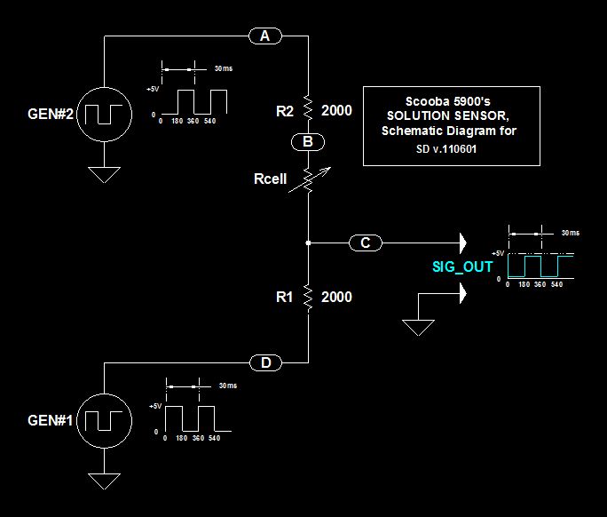
Scoobas Solution Sensing Tactic
This document serves multiple purposes, primarily to document the methods employed by a Scooba robot to detect: a) the presence of an acceptable cleaning solution being delivered to its pump, and b) the excess presence of used solution collected off...

Wire Break Sensor Alarm Circuit Schematic
The circuit of a loop sensor-based simple security alarm is described here. The sensor loop consists of a short length of thin enamelled copper wire.
The loop sensor security alarm operates on the principle of detecting interruptions in the circuit formed...

Automatic Room light Control With Bi Directional Visitor Counter
The objective of this project is to create a controller-based model that counts the number of individuals entering a specific room and activates the lighting accordingly. This is achieved through the use of sensors that detect the current number of...

Add a sensor to a board and measure something with it
This week's plan is to build a device that warns of the potential for a knockdown, which is the process by which an over-canvassed ship is laid over on her beam-ends. The risk of sinking is high during this event,...
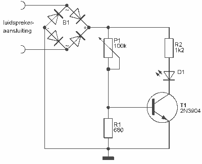
Audio Peak / Beat LED indicator
This indicator can be used, or see if your speakers can be damaged by the noise power. With P1 you can set the limit to which D1 LED lights. The pot is 100k here, you can even experiment with other...

Field disturbance sensor-alarm
The change in ambient light triggers the alarm by changing the resistance of LDR1 and LDR2.
The circuit utilizes two light-dependent resistors (LDR1 and LDR2) to detect variations in ambient light levels. LDRs are passive components that exhibit a change in...

Sensor-Activated Relay Pulser Circuit
A sensor activates transistor Q1 to turn on the low-frequency 555 oscillator, which generates pulses to control LAMP II. The sensor may respond to variations in light or temperature. Either resistor RA or RB can function as the sensor, depending...

Gate automatic lamp circuit
The circuit utilizes multiple integrated circuits to form an automatic lighting device that is activated by door and window sensors. It includes CD4093 digital integrated circuits, a relay, and a power supply circuit. The system typically remains closed when a...