


Plant water gauge

Description: To calibrate the gauge, connect the battery and press the probes gently into a pot containing a plant that is just on the verge of needing water (insert it so that only an inch of the probe is left visible at the top). Turn the potentiometer until the "OK" LED lights, then turn it back to the point where that LED goes out and the "W", or "Water", LED just comes on. The device should now be properly adjusted.
The calibration process for the gauge involves a few critical steps to ensure accurate moisture detection in potted plants. Initially, the device must be powered by connecting it to a suitable battery. This connection activates the internal circuitry, allowing the gauge to function properly.
The next step involves inserting the probes into the soil of a plant that is nearing the point of requiring water. It is essential to insert the probes deep enough to ensure they make contact with the moisture level in the soil, while leaving approximately one inch of the probe visible above the soil surface. This placement is crucial as it directly influences the readings obtained from the gauge.
Once the probes are positioned correctly, the user must adjust the potentiometer, which is a variable resistor that allows fine-tuning of the gauge's sensitivity. By turning the potentiometer, the user should observe the "OK" LED indicator. The goal is to adjust this LED to light up, indicating that the device is calibrated to recognize the moisture level when the plant is adequately watered.
After achieving the "OK" state, the potentiometer should be turned back slightly until the "OK" LED turns off. At this point, the "W" or "Water" LED should illuminate, signaling that the soil moisture level has dropped to a point where the plant requires watering. This dual LED indication system provides a clear visual feedback mechanism for the user, ensuring that the calibration is both intuitive and effective.
Upon completion of these steps, the device should be accurately calibrated to provide reliable moisture readings, enabling optimal care for the plant by preventing over or under-watering. Regular checks and recalibrations may be necessary, especially in varying environmental conditions or with different plant species.To calibrate the gauge, connect the battery and press the probes gently into a pot containing a plant that is just on the verge of needing water (stick it in so that only an inch of the probe is left visible at the top). Turn the potentiometer until the "OK" LED lights and then turn it back to the point where that LED goes out and the ''W", or ' 'Water", LED just comes on.
The device should now be properly adjusted.
The calibration process for the gauge involves a few critical steps to ensure accurate moisture detection in potted plants. Initially, the device must be powered by connecting it to a suitable battery. This connection activates the internal circuitry, allowing the gauge to function properly.
The next step involves inserting the probes into the soil of a plant that is nearing the point of requiring water. It is essential to insert the probes deep enough to ensure they make contact with the moisture level in the soil, while leaving approximately one inch of the probe visible above the soil surface. This placement is crucial as it directly influences the readings obtained from the gauge.
Once the probes are positioned correctly, the user must adjust the potentiometer, which is a variable resistor that allows fine-tuning of the gauge's sensitivity. By turning the potentiometer, the user should observe the "OK" LED indicator. The goal is to adjust this LED to light up, indicating that the device is calibrated to recognize the moisture level when the plant is adequately watered.
After achieving the "OK" state, the potentiometer should be turned back slightly until the "OK" LED turns off. At this point, the "W" or "Water" LED should illuminate, signaling that the soil moisture level has dropped to a point where the plant requires watering. This dual LED indication system provides a clear visual feedback mechanism for the user, ensuring that the calibration is both intuitive and effective.
Upon completion of these steps, the device should be accurately calibrated to provide reliable moisture readings, enabling optimal care for the plant by preventing over or under-watering. Regular checks and recalibrations may be necessary, especially in varying environmental conditions or with different plant species.To calibrate the gauge, connect the battery and press the probes gently into a pot containing a plant that is just on the verge of needing water (stick it in so that only an inch of the probe is left visible at the top). Turn the potentiometer until the "OK" LED lights and then turn it back to the point where that LED goes out and the ''W", or ' 'Water", LED just comes on.
The device should now be properly adjusted.

Light Chaser I
Up to 100 lights, LEDs, or optocoupler triac circuits can be sequentially activated by this circuit. One (U1) 4017 decodes and sequences 10 LEDs, whose common anode is returned through a second (U2) CD4017, which counts at one-tenth of the...

LED Flasher Schematic
Here is the new flasher circuit schematic. It consists of a 555 timer circuit and a power transistor. The power transistor is likely over-specified, as it is rated at 10A, but it is the component that was available. The values...

Fading LEDs schematic
This circuit is used to slowly illuminate and fade a pair of red LEDs (light emitting diodes). The fading LEDs could be installed as 'eyes' in a small pumpkin or skull as a Halloween attraction, or mounted in a Christmas...

Electronic dice with 7 LED
This project takes advantage from -HOLD input, which is connected to push-button P1. As long as the -HOLD input is low, truth table's timeouts have no effect because this input serves to disable any state change provoked by timers. The...
fun electronic circuits
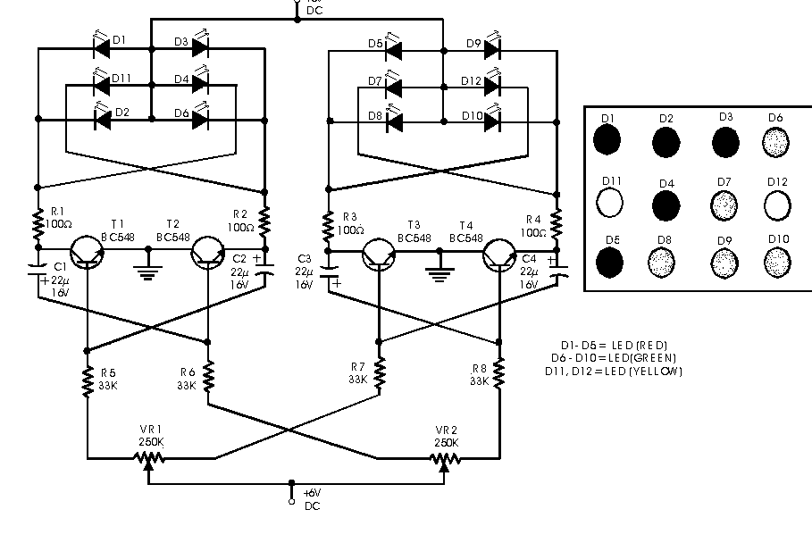
This circuit serves as a decorative element or indicator, featuring adjustable flashing or dancing speeds of LEDs and the ability to create various light patterns. It comprises two astable multivibrators; the first is constructed using transistors T1 and T2, while...

Propeller Clock Mechanically Scanned LED Clock
A motor spins the "propeller", and a small microprocessor keeps track of time and changes the pattern on seven LEDs with exact timing to simulate a 7 by 30 array of LEDs. It is an illusion, but it works nicely.
The...

Electronics Circuits Reference Archive Audio LED VU meter
The circuit is designed to operate with an audio power amplifier that uses 18V-0V-18V power rails. The specific voltage is not critical, but the feedback is referenced to an LED chain connected to a 12V rail, necessitating a separate stabilizer...

High Volt LED Flasher
This is a flasher circuit that directly derives power from AC to produce brilliant flashes at a rate of one flash per second. It utilizes a DIAC as the main element.
The flasher circuit operates by converting alternating current (AC) into...
15v led flasher version b
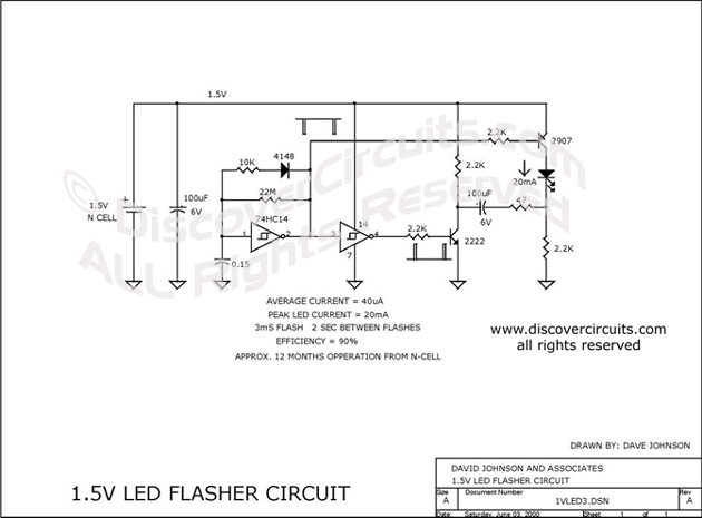
This circuit is designed to extract additional energy from an alkaline battery cell by incorporating two transistors into a configuration similar to a previously mentioned design, thereby enhancing efficiency. A standard 1.5-volt alkaline N cell is capable of powering an...