


Precision Dark-Activated Switch With Hysteresis Circuit
#dark-activated switch
#GdS cell
#bridge circuit
#hysteresis
#relay
#light sensor
#potentiometer
#trip point adjustment
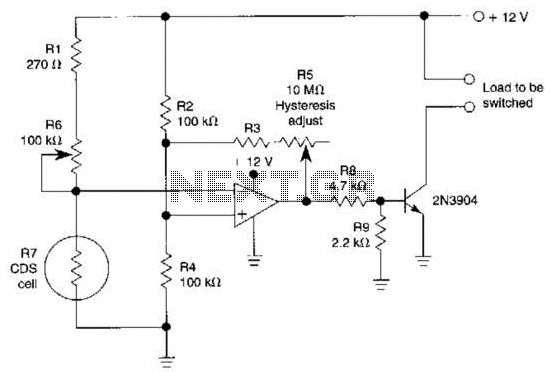
Description: A GdS cell serves as one leg of a bridge circuit. Potentiometer R6 in another leg establishes the trip point. Potentiometer R5 allows for hysteresis adjustment to prevent chattering or hunting of the relay. The light level must increase significantly before the 2N3904 transistor turns off, resulting in the deactivation of the circuit.
The described circuit utilizes a GdS (Gallium Sulfide) light sensor, which is sensitive to changes in light levels. In this configuration, the GdS cell is integrated into a bridge circuit, which typically consists of four resistive elements arranged in a diamond shape. The bridge circuit is designed to measure the imbalance created by changes in light intensity, which affects the resistance of the GdS cell. This imbalance generates a voltage difference across the bridge, which can be monitored.
Potentiometer R6, positioned in one leg of the bridge, is used to set a specific trip point. This trip point determines the threshold at which the circuit responds to changes in light intensity. By adjusting R6, the user can define the sensitivity of the circuit, allowing it to activate or deactivate based on the desired light level.
Potentiometer R5 is incorporated into the circuit to provide hysteresis. Hysteresis is a critical feature that helps stabilize the operation of the relay by preventing rapid on-off cycling, often referred to as chattering or hunting. This is achieved by introducing a delay in the turn-off point of the circuit, ensuring that the light level must increase significantly beyond the trip point before the transistor 2N3904 turns off. This design consideration is crucial in applications where stable operation is necessary, such as in lighting control systems or automatic light sensors.
The 2N3904 transistor functions as a switching element in this circuit. When the light level falls below the defined trip point, the transistor is activated, allowing current to flow through the relay, which in turn can control larger loads. Conversely, when the light level rises sufficiently, the transistor turns off, deactivating the relay and stopping the current flow. This behavior ensures that the circuit responds effectively to changes in ambient light conditions while maintaining reliable operation. A GdS cell is one leg of a bridge circuit. Potentiometer R6 iri another leg sets the trip point. Potentiometer R5 provides hysteresis adjustment to prevent chattering or hunting of the relay. The light level has to increase noticeably before the 2N3904 turns off and the circuit deactivates.
The described circuit utilizes a GdS (Gallium Sulfide) light sensor, which is sensitive to changes in light levels. In this configuration, the GdS cell is integrated into a bridge circuit, which typically consists of four resistive elements arranged in a diamond shape. The bridge circuit is designed to measure the imbalance created by changes in light intensity, which affects the resistance of the GdS cell. This imbalance generates a voltage difference across the bridge, which can be monitored.
Potentiometer R6, positioned in one leg of the bridge, is used to set a specific trip point. This trip point determines the threshold at which the circuit responds to changes in light intensity. By adjusting R6, the user can define the sensitivity of the circuit, allowing it to activate or deactivate based on the desired light level.
Potentiometer R5 is incorporated into the circuit to provide hysteresis. Hysteresis is a critical feature that helps stabilize the operation of the relay by preventing rapid on-off cycling, often referred to as chattering or hunting. This is achieved by introducing a delay in the turn-off point of the circuit, ensuring that the light level must increase significantly beyond the trip point before the transistor 2N3904 turns off. This design consideration is crucial in applications where stable operation is necessary, such as in lighting control systems or automatic light sensors.
The 2N3904 transistor functions as a switching element in this circuit. When the light level falls below the defined trip point, the transistor is activated, allowing current to flow through the relay, which in turn can control larger loads. Conversely, when the light level rises sufficiently, the transistor turns off, deactivating the relay and stopping the current flow. This behavior ensures that the circuit responds effectively to changes in ambient light conditions while maintaining reliable operation. A GdS cell is one leg of a bridge circuit. Potentiometer R6 iri another leg sets the trip point. Potentiometer R5 provides hysteresis adjustment to prevent chattering or hunting of the relay. The light level has to increase noticeably before the 2N3904 turns off and the circuit deactivates.

Light sensor switch circuit
This light sensor switch circuit enables the automatic activation of a lamp when ambient light levels decrease, such as during nightfall. The duration for which the lamp remains on can be adjusted using potentiometer P1, with a range of 1...
Most Popular Circuits
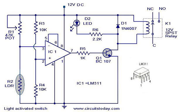
A simple light-activated switch circuit diagram utilizes the National Semiconductor comparator IC LM311 and a light-dependent resistor (LDR). The circuit functions as a voltage comparator, with the non-inverting input of IC1 receiving a reference voltage of 6V through resistors R3...

Basic Transistor Circuits
This circuit is designed to drive a relay coil using a low power output, typically from an integrated circuit (IC) such as a 555 timer or a TTL/CMOS device. It facilitates the switching of high loads or loads requiring AC...

Lights-On Reminder Circuit
A relay and two diodes are all that is needed; the relay performs the job of a buzzer, so no annunciator is required. When the lights are left on while the ignition is off, the normally closed relay contacts are...

Relay Circuit Detects Light Change
Configured with capacitive coupling by inserting a small capacitor between the phototransistor and the bipolar transistor, this relay circuit will respond only to rapid changes.
This relay circuit utilizes capacitive coupling to enhance its responsiveness to fast signal changes. The configuration...

home-made light-operated camera trigger
This device is designed to capture images of moving objects by activating a camera or flashgun when one or two light beams are interrupted. Originally intended for photographing insects in flight, it can also be utilized for projectiles and other...
relay In a circuit being switched by an NPN transistor do power supply and input need the same ground
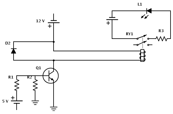
Create a circuit that enables the activation of a relay to control an LED. The relay operates at 12 V, while the available input voltage is 5 V. An NPN transistor will be utilized to switch the power to the...

jk electrical lighting sound systems
Utilizing a relay allows for a reduction in the length of thick wires that need to be routed, particularly through the firewall and beneath the dashboard. This approach also minimizes the necessity for a larger switch. However, when integrating with...

Relay Output Proximity Sensor
Q1 is used as an oscillator operating at approximately 300 kHz. Resistor R9 is configured to allow the oscillator to initiate its operation. An object near the antenna will load the circuit, causing the oscillations to cease. This change is...