


Proportional-temperature-controller
#temperature controller
#pulse snatching
#zero crossing
#TMOS Power FET
#voltage-to-frequency converter
#triac optoisolator
#heater control
#line noise reduction

Description: This temperature controller functions as a pulse snatching device, enabling it to operate at its own speed and activate at the zero crossing of the line frequency. The zero crossing activation minimizes the generation of line noise transients. A TMOS Power FET, Q1, is utilized to control the heater. The temperature sensor D6 generates a DC voltage that is proportional to the temperature, which is then fed into a voltage-to-frequency converter, U1. The output from U1 is a pulse train that corresponds to the temperature offset, which is directed to the input of the triac optoisolator, U2. The anode supply for the triac is a 28 V peak-to-peak, full-wave rectified sine wave. The optoisolator combines the pulse train from U1 with the zero crossing of U2's anode supply, providing a gate turn-on signal for Q1. Consequently, the TMOS power FET Q1 can only activate the heater at the zero crossing of the applied sine wave. The maximum temperature, constrained by the sensor and the insulation of the wire, is 130°C for the components specified.
The temperature controller circuit is designed to efficiently manage the heating element while minimizing electrical noise. At the core of this design is the TMOS Power FET (Q1), which serves as a switching device for the heater. It is activated only at the precise moment when the AC line voltage crosses zero, a technique known as zero crossing turn-on. This method is critical as it reduces electromagnetic interference (EMI) that can arise from abrupt switching.
The temperature sensor (D6) is a key component in this system, providing real-time feedback on the temperature. It outputs a DC voltage that varies with temperature, which is then processed by the voltage-to-frequency converter (U1). This IC translates the varying voltage into a frequency-modulated signal, producing a pulse train that is directly proportional to the temperature offset. This pulse train is essential for controlling the timing of the heater activation.
The triac optoisolator (U2) plays a vital role in isolating the control circuitry from the high-voltage AC line. It receives the pulse train from U1 and combines it with the zero crossing of its anode supply, effectively synchronizing the control signal with the AC waveform. This synchronization ensures that Q1 is only triggered to turn on the heater when the line voltage is at zero, further minimizing noise and ensuring safe operation.
The anode supply for the triac, specified as a 28 V peak-to-peak, full-wave rectified sine wave, provides the necessary voltage levels for the optoisolator to function correctly. The system is designed to handle a maximum temperature of 130°C, a limit determined by the specifications of the temperature sensor and the insulation properties of the wiring used in the circuit.
This temperature control circuit is particularly suitable for applications requiring precise temperature regulation while maintaining low electrical noise, making it ideal for sensitive electronic environments.This temperature controller operates as a pulse snatching device, which allows it to run at its own speed and tum on at the zero crossing of the line frequency. Zero crossing tum-on reduces the generation of line noise transients. TMOS Power FET, Ql, is used to tum on a heater. Temperature sensor D6 provides a de voltage proportional to temperature that is applied to voltage-tofrequency converter Ul.
Output from Ul is a pulse train proportional to temperature offset that is applied to the input of triac optoisolator U2. The anode supply for the triac is a 28 V pk-pk, full-wave rectified sine wave. The optoisolator ORs the pulse train from Ul with the zeroTrossing of U2"s anode supply, supplying a gate tum on signal for Ql. Therefore, TMOS power FET Ql can only tum the heater on at the zero crossing of the applied sine wave.
The maximum temperature, limited by the sensor and the insulation of the wire, is 130°C for the components shown.
The temperature controller circuit is designed to efficiently manage the heating element while minimizing electrical noise. At the core of this design is the TMOS Power FET (Q1), which serves as a switching device for the heater. It is activated only at the precise moment when the AC line voltage crosses zero, a technique known as zero crossing turn-on. This method is critical as it reduces electromagnetic interference (EMI) that can arise from abrupt switching.
The temperature sensor (D6) is a key component in this system, providing real-time feedback on the temperature. It outputs a DC voltage that varies with temperature, which is then processed by the voltage-to-frequency converter (U1). This IC translates the varying voltage into a frequency-modulated signal, producing a pulse train that is directly proportional to the temperature offset. This pulse train is essential for controlling the timing of the heater activation.
The triac optoisolator (U2) plays a vital role in isolating the control circuitry from the high-voltage AC line. It receives the pulse train from U1 and combines it with the zero crossing of its anode supply, effectively synchronizing the control signal with the AC waveform. This synchronization ensures that Q1 is only triggered to turn on the heater when the line voltage is at zero, further minimizing noise and ensuring safe operation.
The anode supply for the triac, specified as a 28 V peak-to-peak, full-wave rectified sine wave, provides the necessary voltage levels for the optoisolator to function correctly. The system is designed to handle a maximum temperature of 130°C, a limit determined by the specifications of the temperature sensor and the insulation properties of the wiring used in the circuit.
This temperature control circuit is particularly suitable for applications requiring precise temperature regulation while maintaining low electrical noise, making it ideal for sensitive electronic environments.This temperature controller operates as a pulse snatching device, which allows it to run at its own speed and tum on at the zero crossing of the line frequency. Zero crossing tum-on reduces the generation of line noise transients. TMOS Power FET, Ql, is used to tum on a heater. Temperature sensor D6 provides a de voltage proportional to temperature that is applied to voltage-tofrequency converter Ul.
Output from Ul is a pulse train proportional to temperature offset that is applied to the input of triac optoisolator U2. The anode supply for the triac is a 28 V pk-pk, full-wave rectified sine wave. The optoisolator ORs the pulse train from Ul with the zeroTrossing of U2"s anode supply, supplying a gate tum on signal for Ql. Therefore, TMOS power FET Ql can only tum the heater on at the zero crossing of the applied sine wave.
The maximum temperature, limited by the sensor and the insulation of the wire, is 130°C for the components shown.

Voltage-To-Frequency Converter I
This voltage-to-frequency converter utilizes a Burr-Brown VFC 32 integrated circuit (IC) and requires minimal components. The circuit values are illustrated in the accompanying figure. This charge-balanced voltage-to-frequency (V/F) converter employs either a VFC32 or a VFC320 IC. The positive charge...

DPP adds versatility to VFC
The basic VFC (voltage-to-frequency converter) in Figure 1 comprises an integrator (IC1) and a Schmitt-trigger circuit (IC2). The integrator converts the dc input voltage, VIN, to a linear voltage ramp, and the Schmitt trigger sets the limits of the integrator's...

Precision oscillator
The RC 4151 precision voltage-to-frequency converter generates a pulse train output that is linearly proportional to the input voltage.
The RC 4151 is a highly accurate voltage-to-frequency converter designed for applications requiring precise frequency output based on varying voltage levels. This...
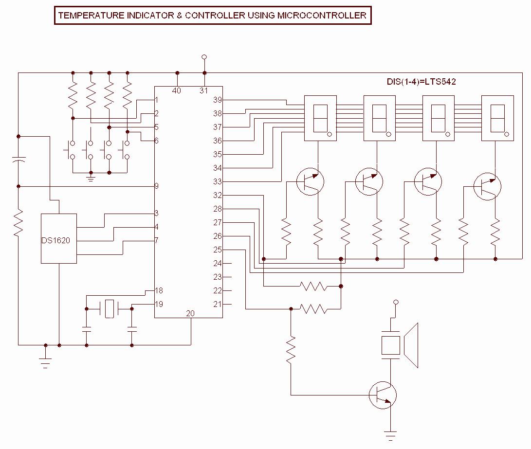
Digital Temperature Controller
This Project is used to indicate the temperature and it is also used as controller. The system will get the temperature from the IC and it will display the temperature over the seven segment display and this temperature was compared...

Low power temperature controller
This circuit was built to stabilize a radio frequency VFO (Variable Frequency Oscillator) for ham radio applications. The circuit has also been used to lower the drift of a Ramsey FM10a micropower FM transmitter. More: The 7805 voltage regulator provides...

Zero crossing switch
When switching loads with a thyristor, significant radio frequency interference (RFI) can occur unless a zero crossing switch is implemented. The circuit illustrates a basic single transistor zero crossing switch. Resistors R1 and R2 function as a potential divider, producing...

High Precision Voltage-to-Frequency Converter (VFC) Using CA3130 Op-Amps
Voltage to frequency conversion is highly beneficial in various applications, such as transmitting temperature measurements using standard voice radio transceivers. This circuit utilizes two CA3130 operational amplifiers, demonstrating satisfactory performance. The linearity of the voltage-frequency transfer is better than 0.5%,...
Heater control
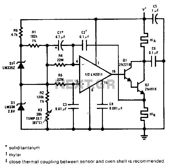
This proportional control crystal oven heater utilizes lead/lag compensation to achieve rapid setting. The time constant can be adjusted using resistor R4 and the compensating resistor R5. It is advisable to use a regulated supply for Q2 if it is...

Simple Stand-Alone Voltage-to-Frequency Converter Using LM231/LM331
A voltage-to-frequency converter can be constructed using the LM231/331 chip, making it a cost-effective solution for applications such as analog-to-digital conversion and frequency-to-voltage conversion over extended periods.
The LM231/331 series of voltage comparators can be effectively utilized to design a voltage-to-frequency...