


Rain Detector Circuit Using NE555
#rain detector
#NE555
#astable multivibrator
#sensor
#audio frequency
#water detection
#PCB design
#electronic projects

Description: This weblog discusses electronic circuit schematics, PCB design, DIY kits, and electronic project diagrams. The rain detector operates on the principle of an astable multivibrator using the 555 timer IC, which is equipped with a sensor capable of detecting water. The astable multivibrator is configured to operate at an audio frequency of 1 kHz. The rain detector circuit can be powered by a voltage source ranging from 5 to 15 VDC. This circuit can be applied in various scenarios, such as in vehicles, to provide protection from rain. The water sensor utilized in the rain detector circuit employs a design that can be created on a PCB, following the path shown in the referenced image. Alternatively, the circuit can be constructed using foil adhered to an insulating plastic board. The key principle of this sensor is its ability to conduct electrical current effectively when its surface comes into contact with even small amounts of water.
The rain detector circuit based on the 555 timer IC is a practical application of basic electronic principles. The astable multivibrator configuration allows the circuit to continuously oscillate between high and low states, generating a square wave output at a frequency of 1 kHz. This oscillation can be used to trigger various actions, such as activating an alarm or turning on a light when rain is detected.
The circuit typically consists of the 555 timer IC, a few resistors, capacitors, and a water sensor. The water sensor is often made from conductive materials that allow for the detection of water by completing an electrical circuit when moisture is present. When water bridges the gap between the sensor's conductive elements, it changes the state of the 555 timer, thereby altering the output signal.
Powering the circuit with a voltage source of 5 to 15 VDC ensures compatibility with a wide range of applications, from small DIY projects to larger installations in vehicles or outdoor equipment. The design can be implemented on a printed circuit board (PCB) for durability and reliability, or can be constructed using simple materials such as foil on an insulated substrate for a more straightforward, cost-effective solution.
In summary, this rain detector circuit is an excellent example of how simple electronic components can be integrated to create a functional device that serves a practical purpose, such as protecting equipment from water damage. The ability to customize the design and easily implement it in various settings makes it a valuable project for electronics enthusiasts and professionals alike.Welcome to the weblog where we discuss about electronic circuits schematics, PCB design, diy kits and electronic projects diagrams. Rain detector using In principle it is an astable multivibrator 555, which is prepared by IC555 with a sensor attached that can detect water.
Astable multivibrator with the 555 is in the audio frequency with a freque ncy of 1 KHz. The use of rain detector circuit can be disupplay 555 with voltage source that is free enough as 5 to 15 VDC. In the application of rain detector circuit The use of this object 555 can be mounted engine, car and others who want to protect from rain.
Water sensor used in the rain detector circuit 555 Using this you can do yourself a PCB Degan make the path as shown in the image above or, as described from the image above is the use foil glued to a board or boards that are plastic insulation. The important principle of this sensor is to conduct electrical current very well when the surface is exposed to water even a little.
The rain detector circuit based on the 555 timer IC is a practical application of basic electronic principles. The astable multivibrator configuration allows the circuit to continuously oscillate between high and low states, generating a square wave output at a frequency of 1 kHz. This oscillation can be used to trigger various actions, such as activating an alarm or turning on a light when rain is detected.
The circuit typically consists of the 555 timer IC, a few resistors, capacitors, and a water sensor. The water sensor is often made from conductive materials that allow for the detection of water by completing an electrical circuit when moisture is present. When water bridges the gap between the sensor's conductive elements, it changes the state of the 555 timer, thereby altering the output signal.
Powering the circuit with a voltage source of 5 to 15 VDC ensures compatibility with a wide range of applications, from small DIY projects to larger installations in vehicles or outdoor equipment. The design can be implemented on a printed circuit board (PCB) for durability and reliability, or can be constructed using simple materials such as foil on an insulated substrate for a more straightforward, cost-effective solution.
In summary, this rain detector circuit is an excellent example of how simple electronic components can be integrated to create a functional device that serves a practical purpose, such as protecting equipment from water damage. The ability to customize the design and easily implement it in various settings makes it a valuable project for electronics enthusiasts and professionals alike.Welcome to the weblog where we discuss about electronic circuits schematics, PCB design, diy kits and electronic projects diagrams. Rain detector using In principle it is an astable multivibrator 555, which is prepared by IC555 with a sensor attached that can detect water.
Astable multivibrator with the 555 is in the audio frequency with a freque ncy of 1 KHz. The use of rain detector circuit can be disupplay 555 with voltage source that is free enough as 5 to 15 VDC. In the application of rain detector circuit The use of this object 555 can be mounted engine, car and others who want to protect from rain.
Water sensor used in the rain detector circuit 555 Using this you can do yourself a PCB Degan make the path as shown in the image above or, as described from the image above is the use foil glued to a board or boards that are plastic insulation. The important principle of this sensor is to conduct electrical current very well when the surface is exposed to water even a little.
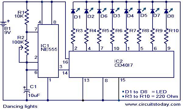
Dancing light
This is a simple dancing light circuit that utilizes the NE555 (IC1) and CD4017 (IC2) integrated circuits. IC1 is configured as an astable multivibrator to generate clock pulses for the CD4017. Each clock pulse received at the clock input (pin...

Gate automatic lamp circuit
The circuit utilizes multiple integrated circuits to form an automatic lighting device that is activated by door and window sensors. It includes CD4093 digital integrated circuits, a relay, and a power supply circuit. The system typically remains closed when a...

Photo Switch Circuit
A simple photo switch circuit using the NE555 IC with a diagram and schematic. This photo switch activates a relay when light intensity exceeds a certain threshold. It serves as a light sensor circuit suitable for both home and industrial...

Simple NE555 IC Testing Circuit
The NE555 is one of the most commonly used timer integrated circuits (ICs). It is a monolithic timing circuit capable of producing accurate and highly stable time delays or oscillations. Similar to general-purpose operational amplifiers, it is reliable, easy to...

With NE555 make double touch light switch 1
The circuit operates using a touch electrode integrated with a base NE555, forming a double touch light switch circuit. It consists of several parts, including a simple capacitive buck converter with components Cl, C2, VDI, and VD2, which together create...

Multifunction adjustable universal time relay (NE555, CD4013) circuit
The multifunction circuit primarily refers to its capability to operate in three modes: "delayed pull," "time release," and "delayed cycle." The term "delay" indicates that the relay is energized after a predetermined time; however, the relay does not activate until...
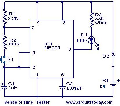
Sense of Time tester circuit
When switch S2 is activated, the circuit functions as an astable multivibrator, causing the LED to illuminate for approximately 0.1 seconds, flashing every 1.5 seconds. Due to the human reaction time being greater than this duration, it is unlikely to...
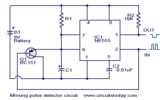
Missing pulse detector circuit using NE555
An NE555 timer integrated circuit (IC) configured in a specific manner can identify the absence of a pulse or an unusually long duration between two successive pulses in a pulse train. Such circuits are applicable for detecting the intermittent operation...

Ding-Dong sound generator
This circuit diagram illustrates a ding-dong sound generator utilizing two NE555 timer integrated circuits (ICs). The design allows for toggling between two adjustable frequencies to create the distinct ding-dong sound. The first NE555 (IC1) is configured as an astable multivibrator...