


Sense Fluid Levels With Capacitance
#capacitance sensing
#fluid level
#CD4538
#CD4011
#monostable multivibrator
#NAND gate
#sensor
#copper foil
#nonmetallic container

Description: This circuit utilizes a CD4538 retriggerable monostable multivibrator in conjunction with a CD4011 NAND chip to detect fluid levels through variable capacitance. The sensor can be constructed using two adhesive copper foil strips placed on a saline or blood supply bag or any non-metallic container. The strips should be positioned as close together and as long as possible, as the capacitance is proportional to the area and inversely proportional to the distance between the strips. When the fluid level is low (CX = C0), the oscillator's frequency is sufficiently high to maintain the trigger input (+TR2) in a retriggered state, thus keeping the output [overbar Q2] low. As the fluid level increases, the capacitance (C) also rises, leading to a decrease in frequency. Potentiometer R3, along with capacitor C3, determines the threshold at which retriggering ceases to be continuous. Consequently, what appears as positive pulses at [overbar Q2] are actually "dropouts" from the low state. Provided that the frequency remains low enough, these pulses will be present at +TR1, ensuring that the second half of IC2 is retriggered for suitable values of resistors R4 and capacitor C2. Typical capacitance values of 50 to 100 pF for CX yield an oscillator frequency ranging from 10 to 30 kHz, influenced by stray capacitance.
This circuit operates by leveraging the principles of capacitance to monitor fluid levels effectively. The CD4538 monostable multivibrator serves as the core timing element, producing output pulses based on the input trigger conditions. The variable capacitance formed by the copper foil strips acts as a sensor, where the capacitance changes with the fluid level. The closer the strips are to each other, the greater the capacitance, which directly impacts the frequency of the oscillator.
In this configuration, the CD4011 NAND gate chip is utilized to process the signals from the monostable multivibrator. The interaction between the two ICs allows for reliable detection and signal conditioning, ensuring that the circuit can accurately reflect changes in fluid levels. The use of a potentiometer (R3) provides an adjustable threshold for the circuit, allowing for calibration based on the specific application and fluid characteristics.
The design emphasizes the importance of selecting appropriate values for the components involved. The choice of capacitor C3 and resistor R4, along with the variable capacitance sensor, directly influences the responsiveness and sensitivity of the fluid level detection. This circuit can be implemented in various applications, including medical devices, industrial fluid monitoring systems, and automated processes where fluid levels need to be tracked and managed efficiently. Overall, this schematic demonstrates an effective approach to fluid level sensing, merging analog components with practical design considerations.This circuit, which uses a CD4538 retriggerable monostable multivibrator and a CD4011 NAND chip, can sense fluid levels using a variable capacitance ( see the figure ). Such a sensor can be as simple as two adhesive copper foil strips on a saline or blood-supply bag or on another nonmetallic container.
These strips should be as close together and as long as possible, since C ‰ • (A/L). When the fluid level is low (CX = C0), the oscillator`s frequency is high enough so that the trigger input (+TR2) keeps that half of IC2 retriggered, i. e. [overbar Q2] is kept low. As the fluid level rises, so does C, and in turn the frequency goes down. Potentiometer R3 with capacitor C3 sets the level at which the retriggering is no longer continuous. Therefore, what might look like positive pulses at [overbar Q2] are actually "dropouts" from the low state.
As long as the frequency is low enough, these pulses will appear at +TR1, keeping the second half of IC2 retriggered for appropriate values of R4 and C2. Typical values of 50 to 100 pF for CX will produce an oscillator frequency of 10 to 30 kHz, depending on stray capacitance.
This circuit operates by leveraging the principles of capacitance to monitor fluid levels effectively. The CD4538 monostable multivibrator serves as the core timing element, producing output pulses based on the input trigger conditions. The variable capacitance formed by the copper foil strips acts as a sensor, where the capacitance changes with the fluid level. The closer the strips are to each other, the greater the capacitance, which directly impacts the frequency of the oscillator.
In this configuration, the CD4011 NAND gate chip is utilized to process the signals from the monostable multivibrator. The interaction between the two ICs allows for reliable detection and signal conditioning, ensuring that the circuit can accurately reflect changes in fluid levels. The use of a potentiometer (R3) provides an adjustable threshold for the circuit, allowing for calibration based on the specific application and fluid characteristics.
The design emphasizes the importance of selecting appropriate values for the components involved. The choice of capacitor C3 and resistor R4, along with the variable capacitance sensor, directly influences the responsiveness and sensitivity of the fluid level detection. This circuit can be implemented in various applications, including medical devices, industrial fluid monitoring systems, and automated processes where fluid levels need to be tracked and managed efficiently. Overall, this schematic demonstrates an effective approach to fluid level sensing, merging analog components with practical design considerations.This circuit, which uses a CD4538 retriggerable monostable multivibrator and a CD4011 NAND chip, can sense fluid levels using a variable capacitance ( see the figure ). Such a sensor can be as simple as two adhesive copper foil strips on a saline or blood-supply bag or on another nonmetallic container.
These strips should be as close together and as long as possible, since C ‰ • (A/L). When the fluid level is low (CX = C0), the oscillator`s frequency is high enough so that the trigger input (+TR2) keeps that half of IC2 retriggered, i. e. [overbar Q2] is kept low. As the fluid level rises, so does C, and in turn the frequency goes down. Potentiometer R3 with capacitor C3 sets the level at which the retriggering is no longer continuous. Therefore, what might look like positive pulses at [overbar Q2] are actually "dropouts" from the low state.
As long as the frequency is low enough, these pulses will appear at +TR1, keeping the second half of IC2 retriggered for appropriate values of R4 and C2. Typical values of 50 to 100 pF for CX will produce an oscillator frequency of 10 to 30 kHz, depending on stray capacitance.

Fluid level meter version 2
IC4 serves as a counter and oscillator combination, which is the pivotal component of the circuit. The oscillator generates an AC signal that is output on pin 7. This signal is routed through a voltage divider composed of resistors R3...

HORN CIRCUIT_FOR_MOTORCYCLE_USE
Gates U1-a and U1-b of the 4093 quad 2-input NAND Schmitt trigger are connected in variable, low-frequency square-wave oscillator circuits. The output of gate U1-a is connected to one of the inputs of gate U1-b. The square-wave output of gate...

With a CD4011 dual-produced sound and light control delay lamp circuit
The main circuit utilizes a two-input NAND gate composed of four digital integrated circuits. This includes a NAND gate microphone amplifier circuit, a light control mechanism using an "AND gate," and a monostable delay control circuit formed by NAND gates...

CD4011 dual-produced sound and light control delay lamp circuit
The circuit utilizes CD4011 digital circuits to create a sound-activated light lamp with a dual-control delay section. The left portion of the circuit represents the lighting lines, while the right part consists of the sound and light control delay switch,...

Automatic plant waterer
The unit consists of a sensor, timer, and electric water pump. The sensor is embedded in the soil, and when dry, the electronics operate the water pump for a preset time. The circuit is composed of a level-sensitive Schmitt trigger,...

Cro-doubler
The IC1a, IC1b, and IC1c components of the quad two-input NAND gate 4011 are configured as an astable multivibrator, while IC1d functions as an inverter. Terminals 3 and 11 of the 4011 generate square waves that are out of phase...

Unsteady chain circuit diagram
The 322 monostable multivibrator is configured in a cross-connected manner. When operating under non-steady state conditions with the oscillator Unicom, it generates a continuous timing cycle, as illustrated in the accompanying figure. T represents the total time period of three...
Unsteady chain circuit diagram
The 322 monostable multivibrator is configured in a cross-connected manner. When operating under non-steady state conditions with the oscillator Unicom, it generates a continuous timing cycle, as illustrated in the accompanying figure. T represents the total time period of three...
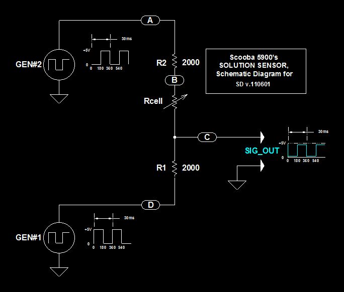
Scoobas Solution Sensing Tactic
This document serves multiple purposes, primarily to document the methods employed by a Scooba robot to detect: a) the presence of an acceptable cleaning solution being delivered to its pump, and b) the excess presence of used solution collected off...