


Sensitive Geomagnetic Sensor circuit
#geomagnetic
#magnetic field
#oscillator
#ferrite rod
#sensor
#audio beat tone
#coil
#medium wave
#probe

Description: This is a rather sensitive circuit which will detect minute variations of a magnetic field, particularly the Earth magnetic field. The principle is based on an audio beat tone generated by two identical oscillators. These must be built in the same manner with the same type of components. In this way we minimize influence from temperature and voltage variations. The two oscillators, called probes, are housed in plastic boxes padded, on the inside, with copper wires terminated in one point only and running parallel to the ferrite rod. This rod, together with the coil was removed from an old Medium Wave radio and a small and powerful magnet was glued on one side. An extra magnet was placed on the outside of one of the boxes in order to set the initial or "zero" beat tone. This magnet is rotated or moved up and down until you hear the right frequency. A small hole is made in each plastic box in order to adjust the trimmer capacitor. Switch S1 will enable the sub-Hertz detector: in this way you will be able to hear the beat note even if the difference between the two probes is below the threshold level of around 20Hz and you will pick up differences well below 1Hz. The two probes are connected to the main box using standard RG58 coaxial cable tested up to a length of 15m. Operating frequency is 1.25MHz and it is sensitive enough to feel the rotation of a speaker magnet 2m away. Battery voltage is 9V.
The circuit design consists of two identical oscillator circuits that are crucial for the detection of minute variations in magnetic fields. Each oscillator is configured to operate at a frequency of 1.25 MHz, providing a stable reference for comparison. The oscillators are enclosed in plastic housings lined with copper wire, which serves to shield the sensitive components from external electromagnetic interference and to enhance the sensitivity of the system.
The oscillators utilize a ferrite rod, salvaged from an old Medium Wave radio, which acts as a magnetic field sensor. A small magnet is affixed to one end of the ferrite rod, allowing the circuit to respond to changes in the magnetic field around it. The sensitivity of the circuit is enhanced by placing an additional magnet externally on one of the oscillator enclosures. This external magnet is adjustable, enabling the operator to fine-tune the initial beat frequency generated by the two oscillators to ensure they are closely matched.
To facilitate adjustments, small access holes are provided in each enclosure, allowing for the calibration of trimmer capacitors. This is essential for achieving optimal performance, as variations in component values due to manufacturing tolerances can affect the beat frequency.
The circuit includes a switch (S1) that activates a sub-Hertz detection mode, enabling the user to hear beat frequencies even when the difference between the two oscillators falls below 20 Hz. This feature allows for the detection of extremely subtle changes in the magnetic field, potentially as low as 1 Hz.
The two oscillator probes are connected to a central processing unit via RG58 coaxial cable, which is suitable for lengths up to 15 meters without significant signal degradation. The entire circuit operates on a 9V battery, ensuring portability and ease of use in field applications. The design is particularly sensitive, capable of detecting the influence of a speaker magnet from a distance of 2 meters, making it a powerful tool for applications involving magnetic field detection and analysis.This is a rather sensitive circuit which will detect minute variations of a magnetic field, particularly the Earth magnetic field. The principle is based on an audio beat tone generated by two identical oscillators. These must be built in the same manner with the same type of components. In this way we minimize influence from temperature and voltage variations. The two oscillators, called probes, are housed in plastic boxes padded, on the inside, with copper wires terminated in one point only and running parallel to the ferrite rod.
This rod, together with the coil was removed from an old Medium Wave radio and a small and powerful magnet was glued on one side. An extra magnet was placed on the outside of one of the boxes in order to set the initial or "zero" beat tone. This magnet is rotated or moved up and down until you hear the right frequency. A small hole is made in each plastic box in order to adjust the trimmer capacitor. Switch S1 will enable the sub-Hertz detector: in this way you will be able to hear the beat note even if the difference between the two probes is below the threshold level of around 20Hz and you will pick up differences well below 1Hz.
The two probes are connected to the main box using standard RG58 coaxial cable tested up to a length of 15m. Operating frequency is 1.25MHz and it is sensitive enough to feel the rotation of a speaker magnet 2m away.
Battery voltage is 9V.
The circuit design consists of two identical oscillator circuits that are crucial for the detection of minute variations in magnetic fields. Each oscillator is configured to operate at a frequency of 1.25 MHz, providing a stable reference for comparison. The oscillators are enclosed in plastic housings lined with copper wire, which serves to shield the sensitive components from external electromagnetic interference and to enhance the sensitivity of the system.
The oscillators utilize a ferrite rod, salvaged from an old Medium Wave radio, which acts as a magnetic field sensor. A small magnet is affixed to one end of the ferrite rod, allowing the circuit to respond to changes in the magnetic field around it. The sensitivity of the circuit is enhanced by placing an additional magnet externally on one of the oscillator enclosures. This external magnet is adjustable, enabling the operator to fine-tune the initial beat frequency generated by the two oscillators to ensure they are closely matched.
To facilitate adjustments, small access holes are provided in each enclosure, allowing for the calibration of trimmer capacitors. This is essential for achieving optimal performance, as variations in component values due to manufacturing tolerances can affect the beat frequency.
The circuit includes a switch (S1) that activates a sub-Hertz detection mode, enabling the user to hear beat frequencies even when the difference between the two oscillators falls below 20 Hz. This feature allows for the detection of extremely subtle changes in the magnetic field, potentially as low as 1 Hz.
The two oscillator probes are connected to a central processing unit via RG58 coaxial cable, which is suitable for lengths up to 15 meters without significant signal degradation. The entire circuit operates on a 9V battery, ensuring portability and ease of use in field applications. The design is particularly sensitive, capable of detecting the influence of a speaker magnet from a distance of 2 meters, making it a powerful tool for applications involving magnetic field detection and analysis.This is a rather sensitive circuit which will detect minute variations of a magnetic field, particularly the Earth magnetic field. The principle is based on an audio beat tone generated by two identical oscillators. These must be built in the same manner with the same type of components. In this way we minimize influence from temperature and voltage variations. The two oscillators, called probes, are housed in plastic boxes padded, on the inside, with copper wires terminated in one point only and running parallel to the ferrite rod.
This rod, together with the coil was removed from an old Medium Wave radio and a small and powerful magnet was glued on one side. An extra magnet was placed on the outside of one of the boxes in order to set the initial or "zero" beat tone. This magnet is rotated or moved up and down until you hear the right frequency. A small hole is made in each plastic box in order to adjust the trimmer capacitor. Switch S1 will enable the sub-Hertz detector: in this way you will be able to hear the beat note even if the difference between the two probes is below the threshold level of around 20Hz and you will pick up differences well below 1Hz.
The two probes are connected to the main box using standard RG58 coaxial cable tested up to a length of 15m. Operating frequency is 1.25MHz and it is sensitive enough to feel the rotation of a speaker magnet 2m away.
Battery voltage is 9V.

Metal detector circuit diagram 3
The metal detector consists of a probe oscillator, a reference oscillator, an audio amplifier, and various other components, as illustrated in the schematic. The probe oscillator is made up of transistors V1 and V2, a detection coil L1, a capacitor...

simple electronic organ
This electronic organ is simple to construct and can provide hours of enjoyment, particularly for children. The circuit is fundamentally an emitter-coupled oscillator consisting of transistors T2 and T3. A square wave voltage can be sampled from the collector of...

Little dipper
The circuit consists of two fundamental components: the oscillator and the detector. The oscillator employs a Field Effect Transistor (FET) in a Colpitts configuration. The energy circulating within the oscillator's tank is coupled through capacitor C4 to the detector circuit,...
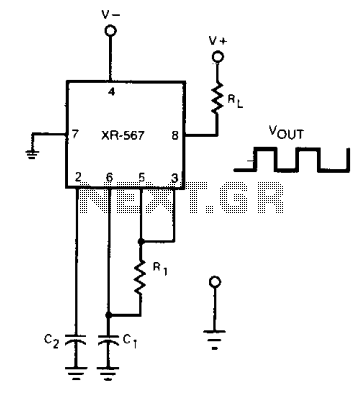
Oscillator with frequency doubled output
The frequency of the current-controlled oscillator can be doubled by feeding a portion of the square-wave output from pin 5 back to the input at pin 3. This configuration allows the quadrature detector to operate as a frequency doubler, resulting...

Metal detector circuit diagram 8
The metal detector circuit consists of a probe oscillator, a PLL (phase-locked loop) circuit, and an audio alarm circuit. The probe oscillator includes a detection coil (L), transistor (V1), and several resistors (R1 to R3) and capacitors (C1 to C5)....

Metallic pipe detector
This circuit employs a 15-kHz oscillator coil. When metal is removed from the energy field, the oscillator voltage is rectified and compared to a reference. A decrease in oscillator voltage activates comparator IC2, causing D4 (LED) to turn off.
L1 consists...

B-Field Measurer
This circuit generates an output voltage that is proportional to the magnetic induction (B) detected by its probe's coil. The coil must be sized to produce a full-scale, 10-V output corresponding to the maximum expected intensity of magnetic induction. The...

Safety flare
When the switch SI is activated, power is supplied to an oscillator that consists of Q1, R1, C1, L1, and L2. Coil L1 serves as the primary winding of transformer T1, while L2 functions as the feedback winding. As Q1...

ring bell electronic circuit
This circuit generates an oscillating frequency of approximately 1 kHz, which can be adjusted by changing the value of resistor R1. The speaker will emit a continuous beep sound at this frequency.
The circuit utilizes a basic oscillator configuration, likely...