


simple water level buzzer circuit

Description: This is a straightforward water level buzzer circuit designed to detect the water level in tanks, pools, washing machines, and similar applications. The circuit features two probes that, upon contact with water, trigger the buzzer to emit a sound. It is an economical design that requires only a few components, including a buzzer, a transistor, a 300K variable resistor, and a 9V battery or power supply. The circuit utilizes a BC547B NPN transistor, though alternative general-purpose transistors such as the 2N2222 or 2N3904 can also be employed. The operation of the water level sensor is uncomplicated; the transistor functions as a switch that activates when the probes detect water, allowing voltage to flow through the transistor and subsequently activating the buzzer.
The water level buzzer circuit operates on a simple principle of conductivity. Two probes are placed at predetermined levels within the water tank or container. When water bridges the gap between these probes, it completes the circuit. The presence of water lowers the resistance between the probes, allowing current to flow. This current is directed to the base of the NPN transistor, in this case, the BC547B.
In this configuration, the transistor acts as a switch. When the probes are submerged in water, the transistor turns on, allowing current to flow from the collector to the emitter. This current flow activates the buzzer connected to the circuit, producing an audible alert. The use of a variable resistor allows for adjustment of the sensitivity of the probes, enabling the circuit to be tailored for different applications, such as varying water levels in different types of tanks or containers.
The overall design of the circuit is compact and cost-effective, making it suitable for DIY projects and educational purposes. The use of general-purpose transistors ensures that the circuit can be easily replicated using readily available components. Additionally, the low power requirement of the circuit allows it to be powered by a standard 9V battery or a compatible power supply, enhancing its versatility for various applications related to water level monitoring.Here is a simple water level buzzer circuit which can be used to detect or sense the level of water in tank, pool, washing machines etc. When the two probes shown in this water level indicator circuit will detect water the buzzer will start producing sound.
The circuit is very simple and low cost using only few parts like Buzzer, Transistor, 300K variable resistor and a 9V battery or power supply. The circuit is using BC547B NPN transistor but you can use any other general purpose transistor in the place of this transistor like 2N2222 or 2N3904. Working of this water level sensor is simple; the transistor used in the circuit is working as a switch.
When the two probes detect water the transistor becomes switched on and as a result the voltage start passing through the transistor, which will activate the buzzer.
The water level buzzer circuit operates on a simple principle of conductivity. Two probes are placed at predetermined levels within the water tank or container. When water bridges the gap between these probes, it completes the circuit. The presence of water lowers the resistance between the probes, allowing current to flow. This current is directed to the base of the NPN transistor, in this case, the BC547B.
In this configuration, the transistor acts as a switch. When the probes are submerged in water, the transistor turns on, allowing current to flow from the collector to the emitter. This current flow activates the buzzer connected to the circuit, producing an audible alert. The use of a variable resistor allows for adjustment of the sensitivity of the probes, enabling the circuit to be tailored for different applications, such as varying water levels in different types of tanks or containers.
The overall design of the circuit is compact and cost-effective, making it suitable for DIY projects and educational purposes. The use of general-purpose transistors ensures that the circuit can be easily replicated using readily available components. Additionally, the low power requirement of the circuit allows it to be powered by a standard 9V battery or a compatible power supply, enhancing its versatility for various applications related to water level monitoring.Here is a simple water level buzzer circuit which can be used to detect or sense the level of water in tank, pool, washing machines etc. When the two probes shown in this water level indicator circuit will detect water the buzzer will start producing sound.
The circuit is very simple and low cost using only few parts like Buzzer, Transistor, 300K variable resistor and a 9V battery or power supply. The circuit is using BC547B NPN transistor but you can use any other general purpose transistor in the place of this transistor like 2N2222 or 2N3904. Working of this water level sensor is simple; the transistor used in the circuit is working as a switch.
When the two probes detect water the transistor becomes switched on and as a result the voltage start passing through the transistor, which will activate the buzzer.

Transistor intercom circuit
This document describes a simple yet effective intercom circuit that is entirely based on transistors. The design features a three-stage RC coupled amplifier. When the pushbutton S2 is activated, the amplifier circuit, which includes transistors T1 and T2, functions as...
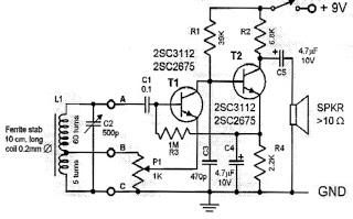
two transistor radio
This circuit is a simple one-transistor Audion type radio powered by a 1.5 V battery. It utilizes a pair of standard low-impedance headphones, wired in series to achieve a total impedance of 64 ohms. The power supply to the circuit...

Magnetic Phono Cartridges Transistor RIAA Preamp
The following two-transistor circuit is a preamplifier for magnetic phono cartridges, characterized by its frequency response defined by the RIAA standard for phono recording. This preamp circuit has a gain of approximately 40 dB (midband) at 1 kHz. The circuit...

Double transistor low noise of the preamplifier measured by high
The Bong ordinary differential amplifier circuit differs from a standard differential circuit by incorporating a voltage-current conversion circuit, which consists of resistors R and Rl. The operational amplifier (OP amp) includes a voltage divider that subsequently converts the voltage into...

transistor based single zone alarm
The circuit incorporates automatic exit and entry delays, a timed bell cut-off, and a system reset feature. It accommodates both normally-open and normally-closed switches and is compatible with standard input devices such as pressure mats, magnetic reed contacts, foil tape,...

Kapanadze 5
The emitter voltage drops completely to 0V from 42V during the pulse when the transistor is conducting or saturated. This contrasts with a pure resistive load (the 4.7 Ohm resistor mentioned in the previous video), where the collector-emitter voltage does...
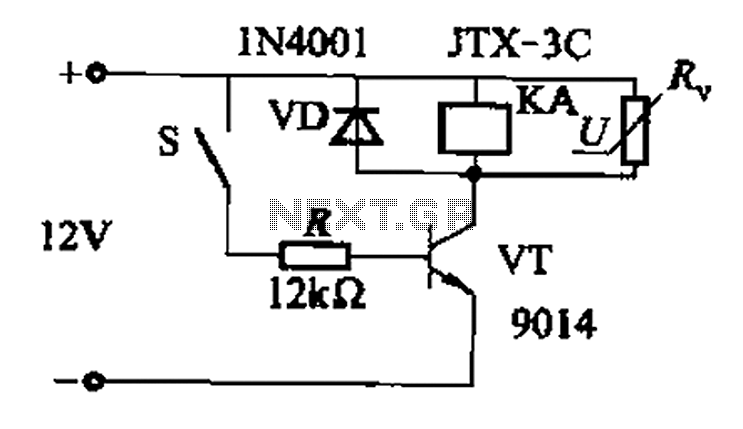
Fast response time of the control transistor circuit b
In a concrete circuit relay application, the transistor VT functions as a high-speed, high-voltage switch. The voltage requirement for switching is 5 to 10 times the rated voltage of the solenoid valve. The circuit is designed for a fast response...

Six a start and stop intermittent cycle control circuits
The circuit illustrated in Figure 3-81 employs a transistor delay circuit to facilitate start-stop cycle control. It can operate in both manual and automatic modes. The circuit is primarily governed by the motor run time circuit, which includes transistors VTi...

Transistor Geiger Counter
One of the most unfortunate features of the typical portable Geiger counter is the short lifespan of the costly high-voltage batteries.
The limitation of high-voltage battery life in portable Geiger counters significantly affects their usability and operational efficiency. These devices are...