


SimpleThermometer
#1-wire
#DS18B20
#thermometer
#temperature sensor
#SMD
#digital sensor
#parasite power
#half-duplex
#driver circuit
#measurement

Description: This circuit is a simple dual simplex to half-duplex driver for 1-wire devices. However, it does not function with all devices, as some may draw excessive current. It was specifically designed and tested for the DS18B20+ 1-wire digital thermometer. The parasite power-only version, DS18B20P, is not supported. The circuit consists of four components, including the thermometer, three 0805 SMD resistors, and a general-purpose PNP transistor. These components are widely available, and kits may sometimes be found within the wlan-si network. The circuit board layout is identical to the previous version, with the positioning of the components adapted to the TP-LINK serial port pinout for easier integration. This documentation serves as a step-by-step guide. Position the circuit board in front of you for proper reading of the markings. Solder two 4.7kΩ resistors into the vertical positions on the left side of the board, labeled R1 and R2. Place the transistor T1 onto the board with its body facing the opposite side (where there are no copper traces), and solder it in place. The rounded part of the transistor body should point towards wlan-si.net. Finally, solder the thermometer into the slot marked IC1, ensuring that the rounded part of the thermometer body also points towards wlan-si.net.
This circuit serves as a dual simplex to half-duplex driver tailored for 1-wire devices, specifically optimized for the DS18B20+ digital thermometer, which is a widely used temperature sensor in various applications. The circuit's design accommodates the operational characteristics of the DS18B20+, ensuring reliable performance while acknowledging limitations with other 1-wire devices that may require higher current than the circuit can provide.
The core components include three 0805 surface mount resistors, which are typically chosen for their small footprint and ease of integration into compact designs. The use of a general-purpose PNP transistor allows for efficient switching and signal modulation necessary for the half-duplex communication protocol utilized by the DS18B20+.
The circuit board layout has been specifically designed to match the TP-LINK serial port pinout, facilitating straightforward connections to existing systems without the need for extensive modifications. This thoughtful design consideration minimizes potential integration challenges, making it accessible for users who may not have advanced electronics skills.
The assembly instructions are clear and methodical, guiding users through the soldering process of the resistors and the transistor. Careful attention is required to ensure that the components are oriented correctly, particularly the rounded ends of the transistor and thermometer, which are critical for proper functionality.
Overall, this circuit provides a practical solution for interfacing with 1-wire devices, particularly in applications where space and integration ease are paramount. The detailed assembly instructions contribute to a user-friendly experience, promoting successful implementation in various electronic projects.This circuit is a simple dual simplex to half-duplex driver for 1-wire devices, although it does not work with all of them, because some draw too much current. It was designed and tested for DS18B20+ 1-wire digital thermometer. The parasite power only version - DS18B20P is not supported. There are four elements plus a thermometer, three 0805 SMD r esistors and a general purpose PNP transistor. These elements are generally available everywhere, there are kits sometimes available within wlan-si network. This circuit board is identical to the previous one, placement of the elements is adapted to the TP-LINK serial port pinout, to enable as painless integration as possible.
This documentation is written as a step by step guide. Place the circuit board in front of you, so you can read the markings normally. Solder 4. 7kOhm resistors on two vertical places on the left side of the board, marked R1 and R2. Place the transistor T1 on the board, so that its body is on opposite side of the board(where are no copper traces) and solder it into place. The rounded part of transistor body has to point in the direction of wlan-si. net. Solder the thermometer on the buard just as you did the transistor into slot marked IC1. The rounded part of thermometer body has to point in the direction of wlan-si. net.
This circuit serves as a dual simplex to half-duplex driver tailored for 1-wire devices, specifically optimized for the DS18B20+ digital thermometer, which is a widely used temperature sensor in various applications. The circuit's design accommodates the operational characteristics of the DS18B20+, ensuring reliable performance while acknowledging limitations with other 1-wire devices that may require higher current than the circuit can provide.
The core components include three 0805 surface mount resistors, which are typically chosen for their small footprint and ease of integration into compact designs. The use of a general-purpose PNP transistor allows for efficient switching and signal modulation necessary for the half-duplex communication protocol utilized by the DS18B20+.
The circuit board layout has been specifically designed to match the TP-LINK serial port pinout, facilitating straightforward connections to existing systems without the need for extensive modifications. This thoughtful design consideration minimizes potential integration challenges, making it accessible for users who may not have advanced electronics skills.
The assembly instructions are clear and methodical, guiding users through the soldering process of the resistors and the transistor. Careful attention is required to ensure that the components are oriented correctly, particularly the rounded ends of the transistor and thermometer, which are critical for proper functionality.
Overall, this circuit provides a practical solution for interfacing with 1-wire devices, particularly in applications where space and integration ease are paramount. The detailed assembly instructions contribute to a user-friendly experience, promoting successful implementation in various electronic projects.This circuit is a simple dual simplex to half-duplex driver for 1-wire devices, although it does not work with all of them, because some draw too much current. It was designed and tested for DS18B20+ 1-wire digital thermometer. The parasite power only version - DS18B20P is not supported. There are four elements plus a thermometer, three 0805 SMD r esistors and a general purpose PNP transistor. These elements are generally available everywhere, there are kits sometimes available within wlan-si network. This circuit board is identical to the previous one, placement of the elements is adapted to the TP-LINK serial port pinout, to enable as painless integration as possible.
This documentation is written as a step by step guide. Place the circuit board in front of you, so you can read the markings normally. Solder 4. 7kOhm resistors on two vertical places on the left side of the board, marked R1 and R2. Place the transistor T1 on the board, so that its body is on opposite side of the board(where are no copper traces) and solder it into place. The rounded part of transistor body has to point in the direction of wlan-si. net. Solder the thermometer on the buard just as you did the transistor into slot marked IC1. The rounded part of thermometer body has to point in the direction of wlan-si. net.

Digital Remote Thermometer
This circuit is designed for precise centigrade temperature measurement. It features a transmitter section that converts the sensor's output voltage, which is proportional to the measured temperature, into frequency. The output frequency bursts are transmitted through the mains supply cables....

A Scriptable Thermometer
A new generation of intelligent, scriptable sensors/controllers is on the horizon. Traditionally, many simple machines utilized separate thermometer and control units. In contrast, this design presents a unified thermometric controller that can be programmed with simple scripts. It incorporates an...

Digital thermometer circuit based on CA3162 CA3162 and LM35
A simple digital thermometer circuit without a microcontroller and featuring a seven-segment LED readout is presented. The circuit utilizes three integrated circuits (ICs): CA3162, CA3161, and LM35. The CA3162 is a monolithic analog-to-digital (A/D) converter with a BCD output. This...

Electronic Thermometer Circuit
There are many digital thermometers with ±1°C displays, but their accuracy is approximately ±1°C and they cannot be calibrated. A thermometer circuit was created using components available at a local electronics hobby shop, providing an educational experience. For a simple...

Coffee thermometer circuit
Measuring the temperature of coffee is important because the taste of coffee relies on two main factors: the strength of the coffee and its temperature.
Measuring the temperature of coffee can be accomplished using a simple electronic circuit designed to provide...

Digital-Output Sensor Simplifies Temperature Acquisition
The TMP03 is a complete temperature data-acquisition system on a monolithic silicon chip. Including a silicon-based sensor, internal voltage reference, and sigma-delta A/D converter, it fits in a 3-pin (power, common, and output) TO-92 transistor package. Its digital output is...

The electronic thermometer circuit diagram for blind
Measuring range: room temperature is -10 to 40 degrees Celsius; body temperature is 36 to 41 degrees Celsius; Resolution: room temperature is 0.5 degrees Celsius, body temperature is 0.05 degrees Celsius; error: room temperature <1 degree Celsius, body temperature <0.1 degrees Celsius. When switch S1 is in position 1, it displays the room temperature profile; position 2 displays the body temperature profile. Components V1, R1, R2, RP1, and RP2 form the temperature measurement circuit.
The temperature measurement circuit is designed to monitor and display two distinct temperature ranges: ambient room temperature and body temperature. The circuit operates with a measuring range for room temperature from -10 to 40 degrees Celsius and for body temperature from 36 to 41 degrees Celsius. The resolution of the circuit is fine-tuned to provide accurate readings, with a room temperature resolution of 0.5 degrees Celsius and a body temperature resolution of 0.05 degrees Celsius. The specified error margins indicate a maximum deviation of less than 1 degree Celsius for room temperature measurements and less than 0.1 degrees Celsius for body temperature measurements.
The circuit utilizes a switch, S1, which allows the user to select between the two temperature profiles. In position 1, the circuit outputs the room temperature, while in position 2, it outputs the body temperature. The operational components include a voltage source (V1), resistors (R1, R2), and potentiometers (RP1, RP2) that are integral to the measurement process. Resistors R1 and R2 are likely part of a voltage divider network that aids in scaling the temperature sensor output to a readable format. Potentiometers RP1 and RP2 can be used for calibration purposes, allowing fine adjustments to ensure that the readings are accurate within the specified error margins.
The temperature sensor, which is not explicitly mentioned but is assumed to be part of the circuit, converts temperature changes into an electrical signal that can be processed by the circuit. The output from the sensor is conditioned by the resistive components to produce a voltage level that corresponds directly to the measured temperature. This voltage is then displayed on an appropriate display unit, which could be an analog gauge or a digital readout, depending on the design of the circuit.
Overall, this temperature measurement circuit is a practical solution for monitoring both ambient and body temperatures with high accuracy and user-friendly operation through the selection switch.

IN148 diode temperature measurement circuit
A diode IN4148 temperature circuit is presented. The circuit operates within a temperature range of -25 to 125 degrees Celsius, with an accuracy of 0.5. The core components of the operational amplifier circuit consist of four LMC660 amplifiers. It features...
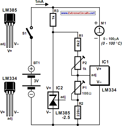
Celsius Thermometer
The circuit for the Celsius thermometer depicted in the diagram is based on the well-known LM334 type from National Semiconductor. This integrated circuit (IC) functions as a sensor that outputs a current directly proportional to the temperature in Kelvin (K)....