


Simply analyse the temperature measurer cipher scheme based on DS18B20 and AT89C2051
#DS18B20
#AT89C2051
#temperature sensor
#nixie tube
#USB power
#microcontroller
#measurement
#display

Description: This project utilizes a USB port for power supply, employs a DS18B20 temperature sensor for data acquisition, and is controlled by an AT89C2051 microcontroller. A common anode quad-digit seven-segment display is used for output, allowing for temperature measurement visualization. The system block diagram is illustrated in Fig. 1. This setup can enhance students' programming skills and design capabilities related to microcontroller applications. Powering the circuit through a USB port enables compatibility with USB adapters or direct connection to a computer's USB port, thereby conserving resources and achieving an optimal operating voltage. The USB port's configuration is depicted in Fig. 3.
The DS18B20's reading and writing sequence and temperature measurement principles are similar to those of the DS1820, with the response time for temperature change reduced from 2 seconds to 750 milliseconds. The temperature measurement principle is shown in Fig. 5. The low-temperature coefficient oscillator's frequency is minimally affected by temperature, producing a pulse signal for counter 1, while the high-temperature coefficient oscillator's frequency varies significantly with temperature, generating pulses for counter 2. The temperature register is preset to correspond with a base figure value of 55. Counter 1 counts the pulse signals from the low-temperature coefficient oscillator, and as its preset value decreases to zero, the temperature register increments by one. This process continues until counter 2 completes its total count, at which point the temperature register reflects the measured temperature.
The slope accumulator in Fig. 5 compensates for nonlinearity during temperature measurement, providing a correction output for counter 1. The system supports multi-point network connections, allowing multiple DS18B20 sensors to be connected in parallel, with three highlighted in this instance, facilitating multi-point temperature measurement. The programming definitions are 9 and 12, with temperature resolutions of 0.5, 0.25, 0.125, and 0.0625 degrees Celsius, enabling high-accuracy temperature measurement. The DS18B20 outputs a digital temperature signal that is transmitted serially to the CPU via a single bus line, with a CRC check for error correction, demonstrating robust interference immunity. The DS18B20 adheres to the one-wire protocol, requiring four initialization steps: sending the ROM command, sending the RAM command, and performing data exchange.
The circuit design integrates these components to create a compact, efficient temperature measurement system suitable for educational purposes and practical applications. The use of USB power supply enhances portability and ease of use, while the microcontroller's programming capabilities allow for customization and experimentation in temperature monitoring projects. The detailed schematic and operational flow can be referenced in the accompanying figures.This making adopts the port as supplying power of USB mouth, carry on the information acquisition of the temperature with DS18B20 temperature sensor, control with AT89C2051 one-chip computer, adopts the common anode nixie tube of quad bit to reveal, thus realize that reveals the system block diagram is shown as in Fig. 1 to the measurement of the temperature. Can train students to improve it to make to originally design with programming ability to the interest that the one-chip computer studies. Adopt USB mouth to supply power, can meet USB adapter USB mouth of circuit boards of people or connect the computer USB port directly.
In this way, not only save resources but also can obtain comparatively ideal working voltage. USB oral appearance and power port define that is shown as in Fig. 3. This making adopts the port as supplying power of USB mouth, carry on the information acquisition of the temperature with DS18B20 temperature sensor, control with AT89C2051 one-chip computer, adopts the common anode nixie tube of quad bit to reveal, thus realize that reveals the system block diagram is shown as in Fig. 1 to the measurement of the temperature. Can train students to improve it to make to originally design with programming ability to the interest that the one-chip computer studies.
Adopt USB mouth to supply power, can meet USB adapter USB mouth of circuit boards of people or connect the computer USB port directly. In this way, not only save resources but also can obtain comparatively ideal working voltage. USB oral appearance and power port define that is shown as in Fig. 3. Reading and writing sequence of DS18B20 and temperature measurement principle is the same as DS1820, figures of the temperature value just got are different, the time delay time that and the temperature changes reduces from 2s to 750ms.
DS18B20 temperature measurement principle shown as in Fig. 5. Among them, the oscillating frequency of Jingzhen of low temperature coefficient is influenced by temperature very small, the pulse signal used for producing fixed frequency gives to the counter 1. The oscillating frequency of Jingzhen of high temperature coefficient changes with temperature variation obviously, signals produced are lost to persons as the pulse of the counter 2.
1 of counters and temperature register presetting in it is getting more correspondent pieces of base figure value in 55. The counter 1 counts the subtraction to the pulse signal emerging in Jingzhen of low temperature coefficient, as the prevalue of the counter 1 reduces inch to for the 0th, value of the temperature register will be added by 1, the counter 1 will be held the person and presetted again, and the beginning counts the pulse signal emerging in Jingzhen of low temperature coefficient again.
Circulate so, until the counter 2 counts one inch of totalizing which stop the temperature register value to OH. At this moment, what the temperature register is hit is numerical to get base measuring temperature. The slope accumulator in Fig. 5 is used for compensating and revising the nonlinearity in the course of temperature measurement, it outputs prevalue used for revising the counter 1.
3It support multi-point network connection function, can connect a plurality of DS18B20 in parallel being only been here three, on the line, realize by network connection multi-point temperature measurement. 6The programming definition is 9 12, correspondent but the resolution temperature is 0. 5, 0. 25, 0. 125 and 0. 0625 respectively, can realize high-accuracy temperature measurement. 8Direct output digit temperature signal, convey to CPU serially with a gleam of bus line, transportable CRC check-up yard at the same time, have extremely strong interference-free correction capabilities.
DS18B20 follows the monobus agreement, there must be 4 pieces of course of initializing, conveying the ROM command, conveying the RAM command, data interchan
The DS18B20's reading and writing sequence and temperature measurement principles are similar to those of the DS1820, with the response time for temperature change reduced from 2 seconds to 750 milliseconds. The temperature measurement principle is shown in Fig. 5. The low-temperature coefficient oscillator's frequency is minimally affected by temperature, producing a pulse signal for counter 1, while the high-temperature coefficient oscillator's frequency varies significantly with temperature, generating pulses for counter 2. The temperature register is preset to correspond with a base figure value of 55. Counter 1 counts the pulse signals from the low-temperature coefficient oscillator, and as its preset value decreases to zero, the temperature register increments by one. This process continues until counter 2 completes its total count, at which point the temperature register reflects the measured temperature.
The slope accumulator in Fig. 5 compensates for nonlinearity during temperature measurement, providing a correction output for counter 1. The system supports multi-point network connections, allowing multiple DS18B20 sensors to be connected in parallel, with three highlighted in this instance, facilitating multi-point temperature measurement. The programming definitions are 9 and 12, with temperature resolutions of 0.5, 0.25, 0.125, and 0.0625 degrees Celsius, enabling high-accuracy temperature measurement. The DS18B20 outputs a digital temperature signal that is transmitted serially to the CPU via a single bus line, with a CRC check for error correction, demonstrating robust interference immunity. The DS18B20 adheres to the one-wire protocol, requiring four initialization steps: sending the ROM command, sending the RAM command, and performing data exchange.
The circuit design integrates these components to create a compact, efficient temperature measurement system suitable for educational purposes and practical applications. The use of USB power supply enhances portability and ease of use, while the microcontroller's programming capabilities allow for customization and experimentation in temperature monitoring projects. The detailed schematic and operational flow can be referenced in the accompanying figures.This making adopts the port as supplying power of USB mouth, carry on the information acquisition of the temperature with DS18B20 temperature sensor, control with AT89C2051 one-chip computer, adopts the common anode nixie tube of quad bit to reveal, thus realize that reveals the system block diagram is shown as in Fig. 1 to the measurement of the temperature. Can train students to improve it to make to originally design with programming ability to the interest that the one-chip computer studies. Adopt USB mouth to supply power, can meet USB adapter USB mouth of circuit boards of people or connect the computer USB port directly.
In this way, not only save resources but also can obtain comparatively ideal working voltage. USB oral appearance and power port define that is shown as in Fig. 3. This making adopts the port as supplying power of USB mouth, carry on the information acquisition of the temperature with DS18B20 temperature sensor, control with AT89C2051 one-chip computer, adopts the common anode nixie tube of quad bit to reveal, thus realize that reveals the system block diagram is shown as in Fig. 1 to the measurement of the temperature. Can train students to improve it to make to originally design with programming ability to the interest that the one-chip computer studies.
Adopt USB mouth to supply power, can meet USB adapter USB mouth of circuit boards of people or connect the computer USB port directly. In this way, not only save resources but also can obtain comparatively ideal working voltage. USB oral appearance and power port define that is shown as in Fig. 3. Reading and writing sequence of DS18B20 and temperature measurement principle is the same as DS1820, figures of the temperature value just got are different, the time delay time that and the temperature changes reduces from 2s to 750ms.
DS18B20 temperature measurement principle shown as in Fig. 5. Among them, the oscillating frequency of Jingzhen of low temperature coefficient is influenced by temperature very small, the pulse signal used for producing fixed frequency gives to the counter 1. The oscillating frequency of Jingzhen of high temperature coefficient changes with temperature variation obviously, signals produced are lost to persons as the pulse of the counter 2.
1 of counters and temperature register presetting in it is getting more correspondent pieces of base figure value in 55. The counter 1 counts the subtraction to the pulse signal emerging in Jingzhen of low temperature coefficient, as the prevalue of the counter 1 reduces inch to for the 0th, value of the temperature register will be added by 1, the counter 1 will be held the person and presetted again, and the beginning counts the pulse signal emerging in Jingzhen of low temperature coefficient again.
Circulate so, until the counter 2 counts one inch of totalizing which stop the temperature register value to OH. At this moment, what the temperature register is hit is numerical to get base measuring temperature. The slope accumulator in Fig. 5 is used for compensating and revising the nonlinearity in the course of temperature measurement, it outputs prevalue used for revising the counter 1.
3It support multi-point network connection function, can connect a plurality of DS18B20 in parallel being only been here three, on the line, realize by network connection multi-point temperature measurement. 6The programming definition is 9 12, correspondent but the resolution temperature is 0. 5, 0. 25, 0. 125 and 0. 0625 respectively, can realize high-accuracy temperature measurement. 8Direct output digit temperature signal, convey to CPU serially with a gleam of bus line, transportable CRC check-up yard at the same time, have extremely strong interference-free correction capabilities.
DS18B20 follows the monobus agreement, there must be 4 pieces of course of initializing, conveying the ROM command, conveying the RAM command, data interchan
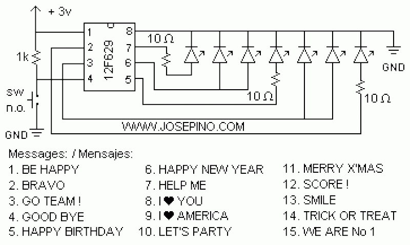
ON/OFF button using Microcontrollers
Using a switch to power up your microcontroller projects may not be a good idea if you need to "wake" the PIC during some events. For example: A metal detector sends a pulse indicating a car is ready to enter...

Temperature To Frequency Converter Circuit
In this circuit, an LM34 or LM35 generates a frequency that is proportional to temperature. The reference current (138) is established through resistor R3. The output can be utilized to drive a display, frequency counter, or other indicating devices for...
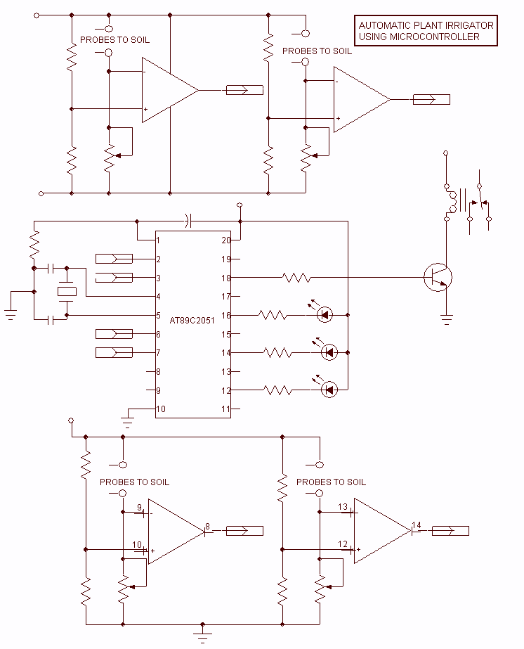
Auto plant Irrigation AT89C2051
The Project presented here waters your plants regularly when you are out for vocation. The circuit comprises sensor parts built using op-amp IC LM324. Op-amps are configured here as a comparator. Two stiff copper wires are inserted in the soil...

Speed Control of DC Motor using Microcontroller by using PWM ECE Project
This report details an electronic project focused on the speed control of a DC motor using a microcontroller and PWM (Pulse Width Modulation). The system integrates a microcontroller with an LCD, keypad, and a DC motor driver. The microcontroller generates...

Simple Circuit Interfaces 1-Wire Temperature Sensor To A Microcontroller
Temperature indicators and temperature-based products have garnered significant interest due to their numerous applications and various possible solutions, each presenting unique advantages and disadvantages. This concept focuses on a sensor interface that delivers high accuracy while minimizing board space. The...

doorbel
This smart doorbell system is designed for use in industrial environments. It is microcontroller-based and controls a horn and a flashlight.
The smart doorbell system utilizes a microcontroller to manage its operations, making it suitable for industrial applications where reliability and...

Thermometer For 5V Operation Circuit
At the core of this circuit is the KTY10 temperature sensor from Siemens. This silicon sensor functions as a temperature-dependent resistor, integrated as one arm of a bridge circuit. A preset potentiometer (P1) is used to balance the bridge at...

TC620 temperature sensor circuit diagram of automatic heating temperature control
The circuit includes the TC620 temperature control circuit, the temperature indicator circuit, a thyristor-controlled heating circuit, a vocal music buck rectifier circuit, and the AC circuit.
The TC620 temperature control circuit is designed to regulate temperature by monitoring the temperature sensor...

Digital Remote Thermometer Circuit With Receiver and Transmitter
This circuit is designed for precise centigrade temperature measurement. It features a transmitter section that converts the sensor's output voltage, which is proportional to the measured temperature, into frequency. The output frequency bursts are transmitted through the mains supply cables....