


Sonar-transducer-switch

Description: This submersible sonar positioning apparatus primarily comprises dual-opposed ultrasonic transducers that are alternately excited, with the return signals processed and displayed for observation and measurement. Typical transmitter frequencies range from 50 to 200 kHz, and pulse widths can be adjusted from 0.3 to 5 ms, depending on the depth and resolution requirements. The input to the transducer/switch is transformer T1, which provides isolation and impedance matching. The turn ratio of the secondary windings is determined by the peak-to-peak amplitude of the transmitter output into the specified load. The transmitted pulse appearing on the secondary winding charges capacitors C1 and C2 through bridge rectifiers D1 and D3. Zener diodes D2 and D4 limit the TMOS gate bias to 12 V; resistors R1 and R2 limit the discharge current from C1 and C2. A square-wave control input is applied to opto-isolators U1 and U2 through resistors R3 and R4. When the control input is at 0 V, U1 is activated; when it changes to +5 V, U2 is activated. When U1 is activated, it saturates and reduces the gate bias to zero, turning off Q1 and Q2. Q3 and Q4 remain on, effectively shunting transducer Z2. Conversely, when U2 is activated, it saturates and reduces the bias to zero, turning off Q3 and Q4, while Q1 and Q2 remain on, effectively shunting transducer Z1.
The submersible sonar positioning apparatus operates by utilizing dual-opposed ultrasonic transducers that alternate in excitation to emit sound waves into the surrounding medium. The return signals from these transducers are processed to determine the distance and positioning of underwater objects. The system is designed to operate within a frequency range of 50 to 200 kHz, which is optimal for sonar applications, providing sufficient resolution for various depths.
Transformer T1 serves a critical role in the system, ensuring that the transducers are appropriately isolated from the driving circuitry while also matching the impedance for efficient energy transfer. The secondary winding's turn ratio is carefully calculated based on the load conditions, allowing for effective energy transfer during transmission.
The bridge rectifiers D1 and D3 convert the alternating current (AC) signal from the transducer output into a direct current (DC) signal, which is then used to charge capacitors C1 and C2. These capacitors store energy, which is essential for maintaining the operation of the transducers and the associated circuitry. Zener diodes D2 and D4 are implemented to regulate the gate bias voltage for the TMOS transistors, ensuring that the system operates within safe voltage limits.
The control mechanism of the apparatus is governed by opto-isolators U1 and U2, which provide electrical isolation between the control signals and the high-voltage components of the circuit. The use of resistors R3 and R4 ensures that the control signals are properly conditioned before reaching the opto-isolators. The activation of U1 and U2 dictates which transducer is active at any given time, allowing for precise control over the sonar system's operation.
In summary, this sonar positioning apparatus is a sophisticated device that integrates various electronic components to achieve effective underwater positioning through the use of ultrasonic technology. The design ensures reliability, safety, and adaptability to different operational environments, making it suitable for various underwater applications, including navigation, exploration, and surveying.This submersible sonar positioning apparatus generally consists of dual-opposed ultrasonic transducers, alternately excited, with return signals processed and displayed for observation and measurement. Typical transmitter frequencies range from 50 to 200J
The transmitted pulse that appears on the secondary winding charges capacitors Cl and C2 through bridge rectifiers Dl and D3. Zener diodes D2 and D4 limit the TMOS gate bias to 12 V; Rl and R2 limit the discharge current from Cl and C2.
The square-wave control input is applied to opto-isolators Ul and U2 through resistors R3 and R4. If the control input is 0 V, Ul is activated; when it changes to +5 V, U2 is activated. When Ul is activated, it saturates and reduces the gate bias to zero, turning Ql and Q2 off. Q3 and Q4 remain on, effectively shunting transducer Z2. When U2 is activated, it saturates and reduces the bias to zero, turning Q3 and Q4 off. Ql and Q2 remain on, effectively shunting transducer Zl.
The submersible sonar positioning apparatus operates by utilizing dual-opposed ultrasonic transducers that alternate in excitation to emit sound waves into the surrounding medium. The return signals from these transducers are processed to determine the distance and positioning of underwater objects. The system is designed to operate within a frequency range of 50 to 200 kHz, which is optimal for sonar applications, providing sufficient resolution for various depths.
Transformer T1 serves a critical role in the system, ensuring that the transducers are appropriately isolated from the driving circuitry while also matching the impedance for efficient energy transfer. The secondary winding's turn ratio is carefully calculated based on the load conditions, allowing for effective energy transfer during transmission.
The bridge rectifiers D1 and D3 convert the alternating current (AC) signal from the transducer output into a direct current (DC) signal, which is then used to charge capacitors C1 and C2. These capacitors store energy, which is essential for maintaining the operation of the transducers and the associated circuitry. Zener diodes D2 and D4 are implemented to regulate the gate bias voltage for the TMOS transistors, ensuring that the system operates within safe voltage limits.
The control mechanism of the apparatus is governed by opto-isolators U1 and U2, which provide electrical isolation between the control signals and the high-voltage components of the circuit. The use of resistors R3 and R4 ensures that the control signals are properly conditioned before reaching the opto-isolators. The activation of U1 and U2 dictates which transducer is active at any given time, allowing for precise control over the sonar system's operation.
In summary, this sonar positioning apparatus is a sophisticated device that integrates various electronic components to achieve effective underwater positioning through the use of ultrasonic technology. The design ensures reliability, safety, and adaptability to different operational environments, making it suitable for various underwater applications, including navigation, exploration, and surveying.This submersible sonar positioning apparatus generally consists of dual-opposed ultrasonic transducers, alternately excited, with return signals processed and displayed for observation and measurement. Typical transmitter frequencies range from 50 to 200J
The transmitted pulse that appears on the secondary winding charges capacitors Cl and C2 through bridge rectifiers Dl and D3. Zener diodes D2 and D4 limit the TMOS gate bias to 12 V; Rl and R2 limit the discharge current from Cl and C2.
The square-wave control input is applied to opto-isolators Ul and U2 through resistors R3 and R4. If the control input is 0 V, Ul is activated; when it changes to +5 V, U2 is activated. When Ul is activated, it saturates and reduces the gate bias to zero, turning Ql and Q2 off. Q3 and Q4 remain on, effectively shunting transducer Z2. When U2 is activated, it saturates and reduces the bias to zero, turning Q3 and Q4 off. Ql and Q2 remain on, effectively shunting transducer Zl.

Medical ultrasonic atomizer 1
The medical ultrasonic atomizer circuit consists of a power supply circuit, an ultrasonic oscillator, and an atomizer circuit, as illustrated in figure 9-110. The power supply circuit includes a timer (Q), a fuse (FU), a current transformer (T), bridge rectifiers...

The built-in ultrasonic flow measurement of stand pipe based on correlation method is designed (
In industrial production, flow measurement is a widely used physical quantity measurement. Under specific circumstances, such as when vertical externally positioned installation probes are required for challenging pipelines like oil wells, it is necessary to design instruments and equipment to...

ultrasonic receiver circuit
The ultrasonic receiver utilized in this circuit is specifically designed to vibrate optimally at a frequency of approximately 40 kHz. Consequently, the transmitter associated with this receiver must also emit waves at 40 kHz. When these waves interact with the...

Ultrasonic Wave Receiver Circuit Schematic Diagram
Ultrasonic receivers detect an ultrasonic signal emitted by an ultrasonic transmitter at a specific frequency. The received signal is filtered using a band-pass filter circuit that allows only the predetermined frequency range to pass. The output signal is then amplified...

Mole Deterrent Teardown
A healthy population of moles exists in the vicinity, prompting the purchase of four inexpensive ultrasonic mole deterrents from eBay to encourage them to relocate. The devices emit a frequency that is unpleasant to moles, leading them to vacate the...
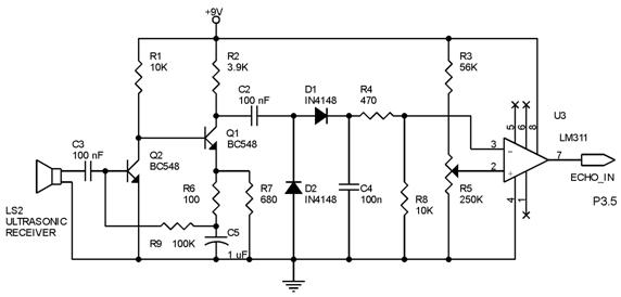
ultrasonic distance measurer
Techniques for an echo sounder used to measure ocean depth can be implemented with an ultrasonic distance measuring device. This device uses a circuit similar to the one described in the previous article, which includes a series of ultrasonic transmitter...

An ultrasonic transmitter circuit diagram discrete components
The discrete components ultrasonic transmitter circuit T/R-40-16 can emit a series of ultrasonic signals at a frequency of 40 kHz. This circuit operates at a voltage of 9V and has a current consumption of 25mA, with a control distance of...
RealView 2.0
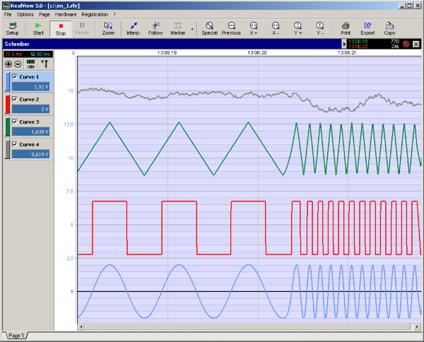
RealView is a measurement application, which records and plots measured values from analogue hardware devices in real-time. Several curves can be plotted into a single diagram. Several diagrams can be arranged on one or more pages if necessary. Plot options...
An ultrasonic transmitter circuit diagram discrete components
The discrete components ultrasonic transmitter circuit T/R-40-16 can emit a series of ultrasonic signals at a frequency of 40 kHz. This circuit operates at a voltage of 9V and has a current consumption of 25mA, with a control distance of...